Middle pan comprehensive measurement gauge of scraper conveyor for coal mine and measurement method using same

A technology of scraper conveyors and comprehensive inspection tools, which is applied in the direction of mechanical measuring devices, mechanical gap measuring, measuring devices, etc., can solve problems that affect product installation and performance, cannot guarantee product quality, and the measurement results are not accurate enough, etc., to achieve The effect of flexible and convenient use, control of product quality, and simplified measurement methods

Active Publication Date: 2012-03-14
CHINA COAL ZHANGJIAKOU COAL MINING MACHINERY
View PDF4 Cites 11 Cited by
  • Summary
  • Abstract
  • Description
  • Claims
  • Application Information

AI Technical Summary

Problems solved by technology

[0002] The traditional method of measuring the middle groove is to measure from both ends of the middle groove with ordinary measuring tools, because the measuring surface of the groove width and the inside and outside of the bent plate and the side of the rail seat are not at the same measurement height, the size and groove width from the inside of the groove width to the inside of the bent plate The dimensions from the inner mouth t

Method used


Image

  • Middle pan comprehensive measurement gauge of scraper conveyor for coal mine and measurement method using same
  • Middle pan comprehensive measurement gauge of scraper conveyor for coal mine and measurement method using same
  • Middle pan comprehensive measurement gauge of scraper conveyor for coal mine and measurement method using same

Examples


Embodiment Construction

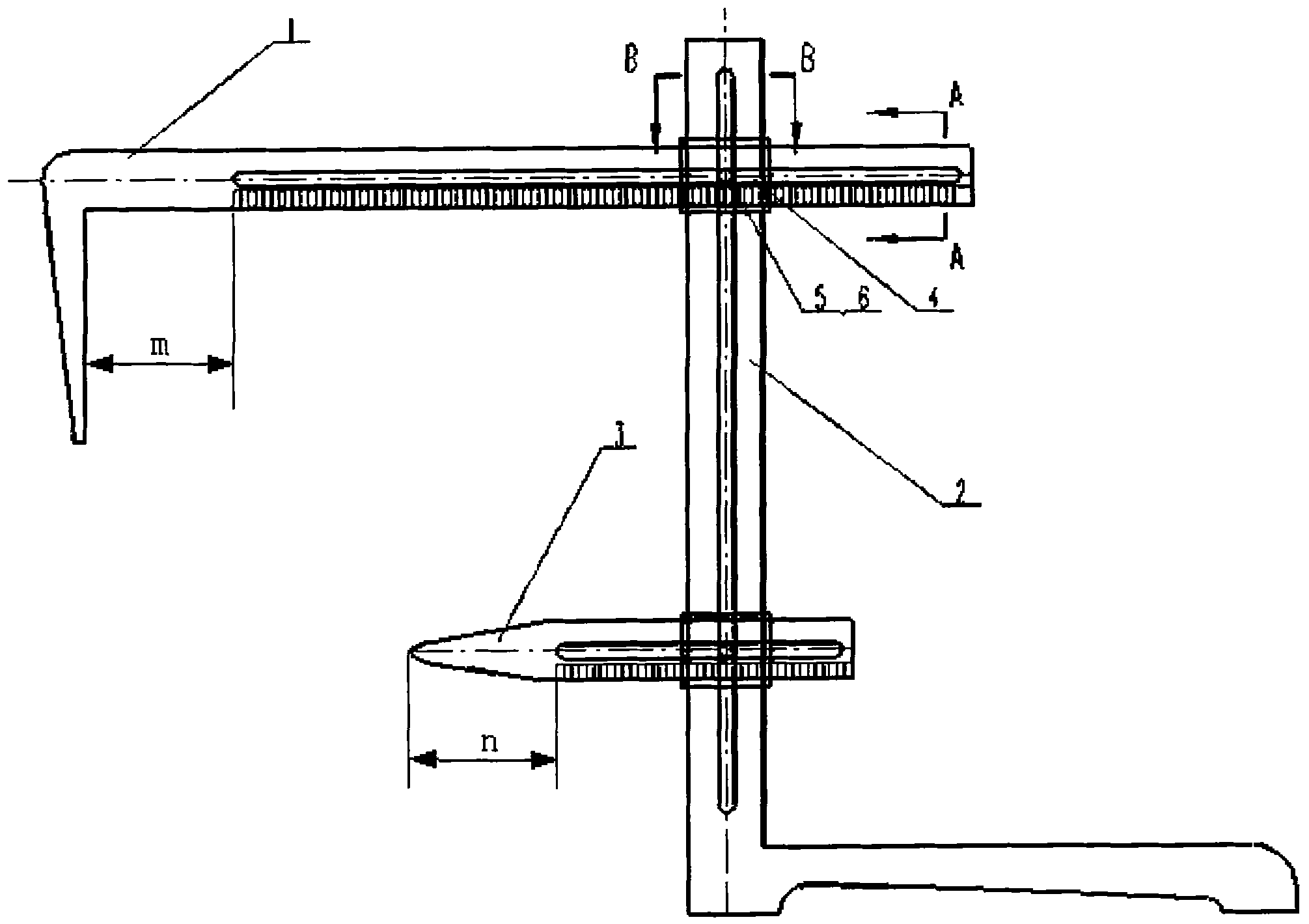
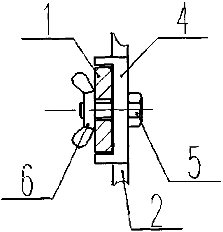
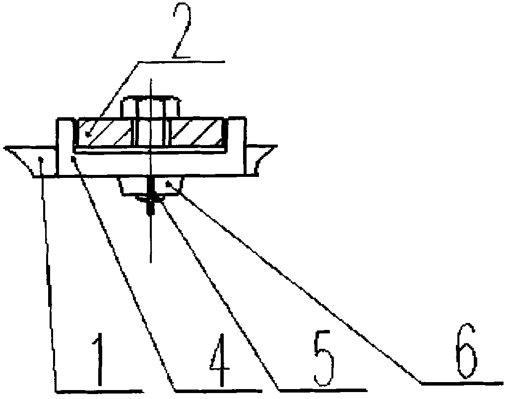
[0021] In the figure: 1 main scale, 2 combination base, 3 auxiliary scales, 4 positioning guide rails, 5 screws, 6 wing nuts;

[0022] a: The horizontal distance from the width of the groove on the middle groove to the inner surface of the rail seat;

[0023] b: The horizontal distance from the inner opening of the upper groove width of the middle groove to the inner side of the bent plate;

[0024] c: the horizontal distance from the inner opening of the upper groove width of the middle groove to the outer side of the bent plate;

[0025] d: rail seat groove width;

[0026] m: the distance from the measuring surface (point) of the main ruler to the zero position of the scale;

[0027] n: the distance from the measuring point of the sub-scale to the zero position of the scale.

[0028] Depend on Figure 1~3 As shown, it is composed of main ruler 1, combined base 2, auxiliary ruler 3, positioning guide rail 4, screw 5 and wing nut 6; The measuring surface is the inner plan...


PUM


Abstract

The invention belongs to the technical field of mechanical finish amount gauges, and relates to a middle pan comprehensive measurement gauge of a scraper conveyor for a coal mine and a measurement method using the same. The middle pan comprehensive measurement gauge comprises a main scale, a combined base, a secondary scale, positioning guide rails, a screw and a thumb nut. The middle pan comprehensive measurement gauge is characterized in that scales are marked on the main scale and the secondary scale, and slots are formed on the main scale and the secondary scale; a measurement face of the main scale is an inner side plane with a left end which is vertical to the main scale, and a distance between the measurement face and a zero mark is 100 mm; a measuring point of the secondary scale is a top point at the left end, and a distance between the measurement point and the zero mark is 100 mm; a slot is formed on an upright scale of the combined base, the bottom faces at both left and right ends of the slot are located on the same horizontal plane, and the upright scale is vertical to the base; two vertical through grooves are formed on the positioning guide rails; the two positioning guide rails pass through the upright scale of the combined base; the main scale and the secondary scale respectively pass through horizontal guide rail grooves of the positioning guide rails and are vertical to the upright scale of the combined base; the main scale is arranged at the upper part of the upright scale, and the secondary scale is arranged at the lower part of the upright scale; and the main scale and the secondary scale are respectively fixed on the upright scale of the combined base by the screw and the thumb nut.

Description

technical field [0001] The invention relates to the technical field of measuring tools for mechanical processing, in particular to a comprehensive measuring tool and a measuring method for a middle groove of a scraper conveyor used in coal mines. Background technique [0002] The traditional method of measuring the middle groove is to use ordinary measuring tools to measure from both ends of the middle groove. Because the measuring surface of the groove width is not at the same measurement height as the inner and outer sides of the bent plate and the side of the rail seat, the dimensions from the inner opening of the groove width to the inner side of the bent plate, and the groove width The dimensions from the inner mouth to the outer side of the bent plate, and the groove width from the inner mouth to the center of the rail seat are all spatial dimensions, which cannot be directly measured. The traditional method is not only difficult to measure, but also takes a long time, ...

Claims


Application Information

Patent Timeline
IPC IPC(8): G01B5/14G01B5/02
Inventor 贺国丰曹跃明杨德顺
Owner CHINA COAL ZHANGJIAKOU COAL MINING MACHINERY
Why Eureka
Try Eureka