Magnetic suspension device capable of automatically rotating

An automatic rotation and magnetic levitation technology, applied in the direction of the magnetic attraction or thrust holding device, electrical components, etc., can solve the problems of high heat generation of the electromagnet, burnout of the power switch, and accelerated product aging, so as to reduce heat generation and ensure safety Sexuality and the effect of prolonging the service life

Inactive Publication Date: 2011-07-06
黄培雄
View PDF6 Cites 27 Cited by
  • Summary
  • Abstract
  • Description
  • Claims
  • Application Information

AI Technical Summary

Problems solved by technology

In the existing magnetic levitation products, even if there is a protection circuit that can pick up the levitation body when the power is off, there is no surge protection circuit, which will easily cause large sparks and burn out the power switch or circuit when starting up
[0004] Existing magnetic levitation products, when working for a long time, the electromagnet often has a high temperature due to high heat generation, which has the problems of high power consumption and accelerated product aging

Method used


Image

  • Magnetic suspension device capable of automatically rotating
  • Magnetic suspension device capable of automatically rotating
  • Magnetic suspension device capable of automatically rotating

Examples


Embodiment 1

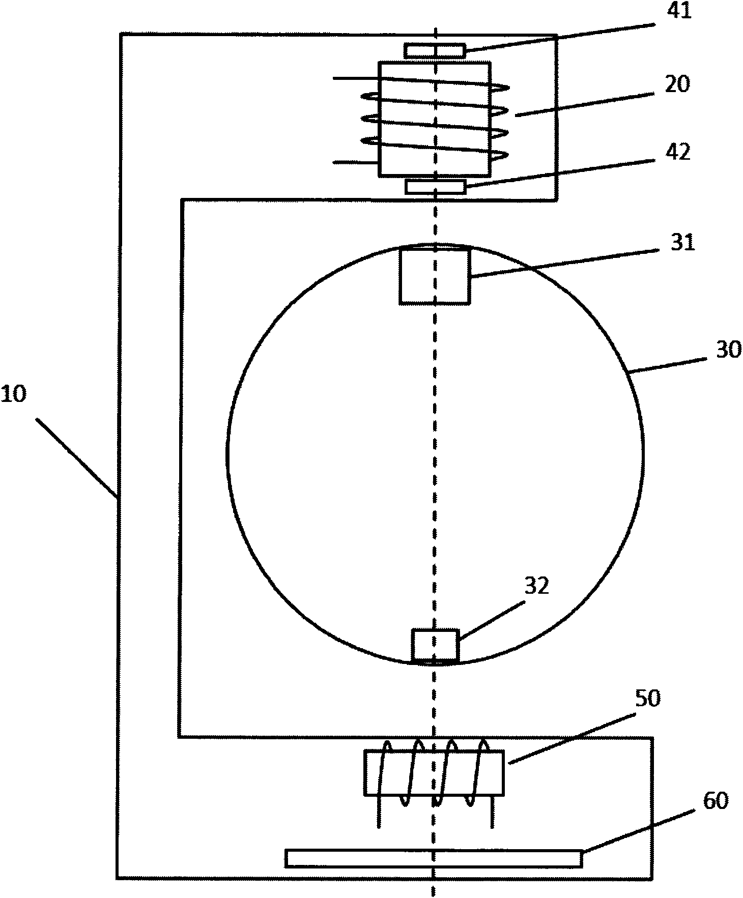
[0031] refer to figure 1 , the self-rotating magnetic levitation device of the present invention includes a support 10 , an electromagnet 20 , a suspension 30 , displacement sensors 41 and 42 , a rotation action coil 50 and a control circuit 60 .

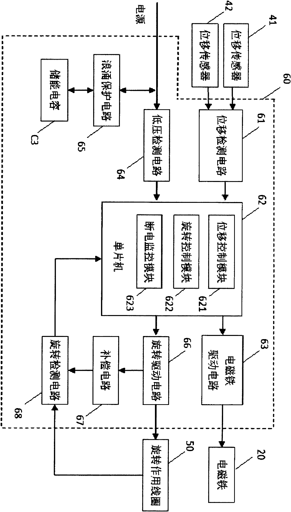
[0032] Such as figure 1 , the support 10 is a hollow frame, which is internally provided with an electromagnet 20, displacement sensors 41 and 42, a rotation action coil 50 and a control circuit 60, and the electromagnet 20, displacement sensors 41 and 42, and the rotation action coil 50 are all connected with the control Circuit 60 is connected.

[0033] The suspended body 30 is a spherical body, such as a floating globe; it can also be a rectangular frame, such as a magnetically suspended photo frame for placing photos, a magnetically suspended advertising display stand, etc.; it can also be other artistic modeling bodies, such as a magnetically suspended Buddha statue. The levitation body 30 is magnetically suspended under the ...

Embodiment 2

[0054] Such as Figure 7 , the bracket 10 is a ceiling structure, and the electromagnet 20, the displacement sensors 41-42, the rotation action coil 50 and the control circuit 60 are arranged inside, and the electromagnet 20, the displacement sensors 41-42 and the rotation action coil 50 are connected with the control circuit 60. The rotating action coil 50 is arranged horizontally according to its magnetic pole direction, close to the rotating permanent magnet 32 ​​and in the same direction. The setting modes of the electromagnet 20 and the displacement sensors 41-42 are all the same as those of the example 1.

[0055] A suspension permanent magnet 31 is arranged in the center of the top of the suspension 30 , and a rotating permanent magnet 32 ​​is arranged horizontally on the top of the suspension 30 away from the center line. The setting method of the suspended permanent magnet 31 is the same as that of the example 1, and the magnetic pole direction of the rotating perman...

Embodiment 3

[0058] This example simplifies Example 1, such as Figure 8 As shown, only a displacement sensor 42 is provided at the lower end of the electromagnet 20 for detecting the magnetic field in the vertical direction, and a unidirectional current drive circuit is used to provide current for the electromagnet 20, as Figure 9 shown.

[0059] Figure 8 Among them, the floating permanent magnet 31 is glued and fixed on the surface of the top center of the floating body 30, and its magnetic pole direction is vertical. The rotating permanent magnet 32 ​​is glued and fixed on the surface at the center of the bottom of the suspension body 30, and its magnetic pole direction is horizontal. The magnetic pole of the lower end of the electromagnet 20 is different from the magnetic pole of the upper end of the suspension permanent magnet 31, that is, the electromagnetic force can only be the suction force.

[0060] When working, the gravity of the suspended body 30 is overcome by the perman...


PUM


Abstract

The invention relates to a magnetic suspension device capable of automatically rotating, which comprises a bracket, an electromagnet, a suspension component, a displacement sensor, a rotating action coil, and a control circuit, wherein the electromagnet is arranged in the bracket; a suspension permanent magnet and a rotating permanent magnet are arranged in the suspension component; the suspension component can be magnetically suspended under the electromagnet and can automatically rotate along two directions; the displacement sensor is arranged in the bracket; the rotating action coil is arranged in the bracket and is used for detecting the rotation of the suspension component and driving the suspension component to rotate; the control circuit is arranged in the bracket; and the electromagnet, the displacement sensor and the rotating action coil are all connected to the control circuit. The suspension component of the device can stably suspend in air and can automatically rotate along two directions, the suspension component is under the power-off protection, and the control structure is simple. The device has the advantages of low power consumption, less emitted heat, and longerservice life. The device provided by the invention can be used as handiwork, showing stand, and the like.

Description

【Technical field】 [0001] The invention relates to a magnetic levitation device, in particular to an automatically rotatable magnetic levitation device that can be used for handicrafts such as a magnetic levitation globe, a magnetic levitation photo frame, a magnetic levitation advertisement display stand, and a levitation Buddha statue. 【Background technique】 [0002] The existing automatic rotating magnetic levitation device generally separates the detection of the rotation of the suspension from the rotation drive. In Chinese patents CN1801595A and CN1599228A, the detection and driving methods of the rotating system are all separated. In the Chinese patent CN101572521A, the rotating system adopts a force-sensitive assembly composed of two sets of coils, one set is used for detection and the other set is used for driving. None of them can realize both sensor detection and rotary drive. [0003] In addition, in the current magnetic levitation device, there is usually no po...

Claims


Application Information

Patent Timeline
Patent Type & Authority Applications(China)
IPC IPC(8): H02N15/00
Inventor 黄培雄
Owner 黄培雄
Why Eureka
Try Eureka