Supercharge Your Innovation With Domain-Expert AI Agents!

Filter switching device

A filter switching and filter technology, applied in optics, installation, optical components, etc., can solve the problem of not being able to know the correct switching of the filter

Inactive Publication Date: 2012-03-14
HONG FU JIN PRECISION IND (SHENZHEN) CO LTD +1
View PDF2 Cites 3 Cited by
  • Summary
  • Abstract
  • Description
  • Claims
  • Application Information

AI Technical Summary

Problems solved by technology

The disadvantage of this design method is that it is impossible to know whether the filter has been switched correctly

Method used


Image

  • Filter switching device
  • Filter switching device
  • Filter switching device

Examples


Embodiment Construction

[0022] Below in conjunction with accompanying drawing and preferred embodiment the present invention is described in further detail:

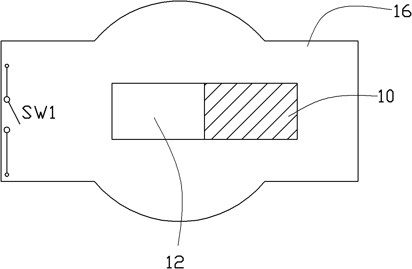
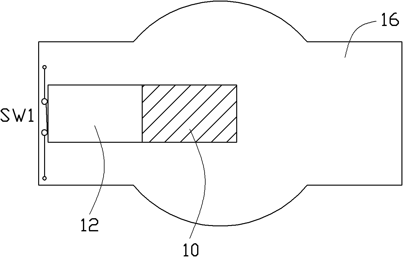
[0023] see figure 1 and figure 2 A preferred embodiment of the filter switching device of the present invention includes a filter 10 for filtering infrared light, a filter 12 for filtering daytime light, a motor M, a base 16, a micro-motion The switch SW1 and a resistor R. The optical filter switching device is installed between the photographic lens and the image sensor of a video camera, so that the photographic lens can select different optical filters when shooting during daytime and nighttime.

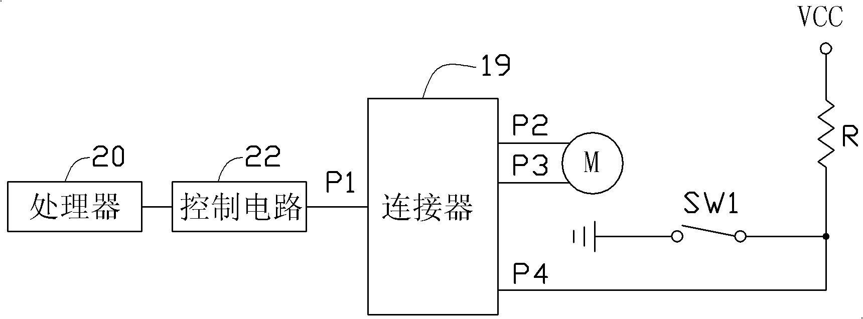
[0024] The motor M and the micro switch SW1 are connected to the processor 20 and the control circuit 22 inside the camera through a connector 19 . The processor 20 outputs different voltage signals to the motor M through the control circuit 22, so that the motor M rotates forward or reversely, thereby adjusting the positions of the two optical...


PUM


Abstract

The invention provides a filter switching device arranged in a camera. The filter switching device comprises a first filter, a second filter, a motor for controlling movement of the two filters according to a processor of the camera, and a microswitch, wherein the microswitch is arranged close to the first filter; the microswitch is closed when the first filter is contacted with the microswitch, and the microswitch is disconnected when the first filter is far away from the microswitch; and one end of the microswitch is grounded, and the other end of the microswitch is connected with a voltage source through a resistor and is also connected with the processor of the camera through a connector.

Description

technical field [0001] The invention relates to a light filter switching device for a video camera. Background technique [0002] In the design of the surveillance camera, in order to be able to record clearly at night, an infrared light source is generally added to the design. Turning on the infrared light source at night can enable the monitoring camera to take pictures. However, the infrared light source will cause the problem of color shift in the image captured by the surveillance camera, so an infrared filter will be added in front of the photosensitive component of the surveillance camera. When the monitoring camera is in the nighttime shooting mode, the infrared filter is selected; when the monitoring camera is in the daytime shooting mode, a filter for filtering daytime light is selected. The disadvantage of this design method is that it is impossible to know whether the filter has been switched correctly. Contents of the invention [0003] In view of the above...

Claims


Application Information

Patent Timeline
IPC IPC(8): G03B17/14G02B7/00H04N5/232
Inventor 谢明志
Owner HONG FU JIN PRECISION IND (SHENZHEN) CO LTD
Features
  • R&D
  • Intellectual Property
  • Life Sciences
  • Materials
  • Tech Scout
  • Unparalleled Data Quality
  • Higher Quality Content
  • 60% Fewer Hallucinations
Learn More