Image processing apparatus and image processing method

An image processing device and pixel technology, applied in the directions of image data processing, image enhancement, image analysis, etc., can solve problems such as difficulty in distinguishing and detecting abnormal parts from groove positions and contour parts, and having no shape.

Inactive Publication Date: 2012-03-14
OLYMPUS CORP
View PDF6 Cites 9 Cited by
  • Summary
  • Abstract
  • Description
  • Claims
  • Application Information

AI Technical Summary

Problems solved by technology

In addition, the second shape-dependent filter in JP-A-2002-99896 is used to emphasize a specific shape (shape of microcalcification shadow), but the abnormal part reflected on the image of the lumen in the living body does not have a definite shape
Therefore, it is difficult to assume the shape of the abnormal part in advance as in Japanese Patent Laid-Open No. 2002-99896, and then design a structure for remaining through the first shape-dependent filter (for example, the aforementioned curved part with a large curvature). ) and the optimal shape-dependent filter for distinguishing abnormal parts
Therefore, even if the two shape-dependent filters are combined, it is difficult to distinguish and detect abnormal parts from groove positions and contour parts

Method used


Image

  • Image processing apparatus and image processing method
  • Image processing apparatus and image processing method
  • Image processing apparatus and image processing method

Examples


Embodiment approach 1

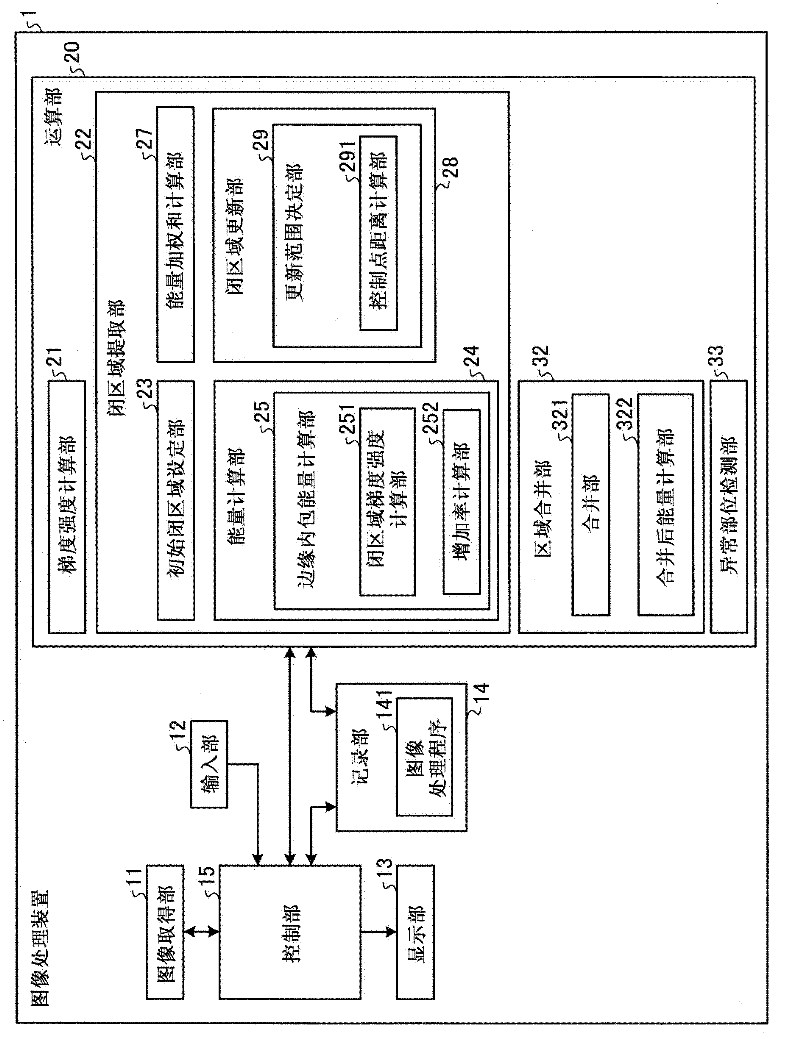
[0051] First, an image processing device according to Embodiment 1 will be described. figure 1 It is a block diagram illustrating the functional configuration of the image processing device 1 according to the first embodiment. The image processing device 1 of Embodiment 1 is, for example, figure 1 It includes an image acquisition unit 11 , an input unit 12 , a display unit 13 , a recording unit 14 , a calculation unit 20 , and a control unit 15 for controlling the overall operation of the image processing device 1 .

[0052] The image acquisition unit 11 is used to acquire the image data of the image of the lumen in the living body captured by the medical observation device, and the image data of the lumen image in the living body acquired by the image acquisition unit 11 is recorded in the recording unit 14, and the image data of the lumen image in the living body acquired by the image acquisition unit 11 is recorded in the recording unit 14, and is transmitted by the computi...

Embodiment approach 2

[0119] First, the configuration of an image processing device according to Embodiment 2 will be described. Figure 15 It is a block diagram illustrating the functional configuration of the image processing device 1a according to the second embodiment. In addition, the same code|symbol is attached|subjected to the structure similar to the structure demonstrated in Embodiment 1. As shown in FIG. The image processing device 1a of Embodiment 2 is, for example, Figure 15 The figure includes an image acquisition unit 11 , an input unit 12 , a display unit 13 , a recording unit 14 a , a calculation unit 20 a , and a control unit 15 that controls the overall operation of the image processing device 1 a.

[0120] An image processing program 141 a for realizing the processing of the second embodiment and detecting an abnormal site from an image of a lumen in a living body is recorded in the recording unit 14 a.

[0121] In addition, the calculation unit 20 a includes a gradient stren...

Embodiment approach 3

[0146] First, the configuration of an image processing device according to Embodiment 3 will be described. Figure 21 It is a block diagram illustrating the functional configuration of the image processing device 1b according to the third embodiment. In addition, the same code|symbol is attached|subjected to the structure similar to the structure demonstrated in Embodiment 1. As shown in FIG. The image processing device 1b of Embodiment 3 is, for example, Figure 21 The figure shown includes an image acquisition unit 11, an input unit 12, a display unit 13, a recording unit 14b, a calculation unit 20b, and a control unit 15 for controlling the overall operation of the image processing device 1b.

[0147] An image processing program 141b for realizing the processing of the third embodiment to detect an abnormal site from an in vivo lumen image is recorded in the recording unit 14b.

[0148] In addition, the calculation unit 20b includes a gradient intensity calculation unit 2...


PUM


Abstract

The invention provides an image processing apparatus and an image processing method. The image processing apparatus includes a gradient strength calculating unit that calculates a gradient strength of a pixel value of each pixel based on an intraluminal image that is a captured image of an intralumen; a closed region extracting unit that extracts a closed region from the intraluminal image, the closed region satisfying conditions that the pixel of which gradient strength is a predetermined value or more is not included in the closed region and a boundary of the closed region does not bend with a predetermined curvature or higher toward an inner side of the closed region; and an abnormal portion detecting unit that detects an abnormal portion inside the closed region. The closed region extracting unit includes an initial closed region setting unit that sets an initial shape of the closed region; an energy calculating unit that calculates values of a plurality of types of energy including at least energy determined by an outer shape of the closed region and energy determined by the gradient strength in the closed region; an energy-weighted sum calculating unit that calculates a weighted sum of the plurality of types of energy; and a closed region updating unit that updates a shape of the closed region within an update range based on the weighted sum. The closed region updating unit includes an update range determining unit that determines the update range in which the shape of the closed region is updated based on any one of the values of the plurality of types of energy.

Description

technical field [0001] The present invention relates to an image processing device and an image processing method for processing an image of a lumen in a living body obtained by photographing a lumen in a living body. Background technique [0002] Conventionally, endoscopes have been widely used as medical observation devices that are introduced into the body of a subject such as a patient to observe the inside of a lumen inside the body. In addition, in recent years, an ingestion-type endoscope (capsule endoscope) having an imaging device inside a capsule casing and a communication device for wirelessly transmitting image data captured by the imaging device outside the body has been developed. Observing and diagnosing images of internal lumens (in vivo lumen images) captured by these medical observation devices requires a lot of experience, so it is desirable to have a medical diagnosis support function that assists doctors in diagnosis. As one of the image recognition tec...

Claims


Application Information

Patent Timeline
Patent Type & Authority Applications(China)
IPC IPC(8): G06T7/00G06T5/00A61B1/00
CPCG06T7/0012G06T2207/30028G06T7/149
Inventor 北村诚神田大和松田岳博河野隆志弘田昌士
Owner OLYMPUS CORP
Why Eureka
Try Eureka