Audio signal receiving and transferring device

An audio signal and switching device technology, applied in the electronic field, can solve the problems of increasing the cost of the electronic device, increasing the volume of the electronic device, low output power of the low-impedance voice coil speaker interface, etc., and achieves the reduction of the volume and the low hardware cost. , the effect of reducing costs

Active Publication Date: 2012-03-14
TENDYRON CORP
View PDF7 Cites 9 Cited by
  • Summary
  • Abstract
  • Description
  • Claims
  • Application Information

AI Technical Summary

Problems solved by technology

[0003] Since the output power of the low-impedance voice coil speaker interface is very small, except for electronic devices with low power consumption (such as headphones), electronic devices that receive audio signals through the ...

Method used


Image

  • Audio signal receiving and transferring device
  • Audio signal receiving and transferring device
  • Audio signal receiving and transferring device

Examples


no. 1 example

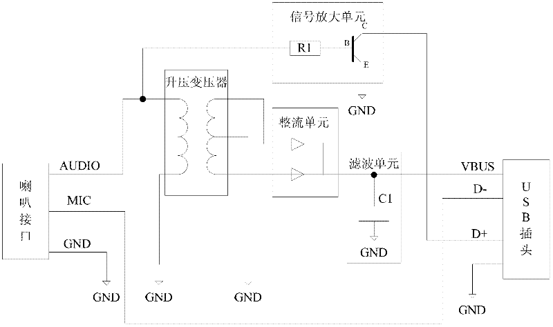
[0088] figure 1 It is a schematic structural diagram of the first embodiment of the audio signal switching device of the present invention; figure 1 As shown, the audio signal conversion device includes: a speaker interface, a booster unit (such as figure 1 Step-up transformer shown), rectification unit, filter unit, USB output interface (such as figure 1 USB plug shown); where:

[0089] The speaker interface is used for connecting with an audio signal sending device (for example, a mobile phone), receiving an audio signal output by the audio signal sending device, and outputting a signal to the audio signal sending device.

[0090] The above-mentioned speaker interface can be a low-impedance voice coil speaker interface (for example, a headphone interface), which includes: audio signal input pins (such as figure 1 AUDIO pin shown), Mic pin (such as figure 1 MIC pin shown), ground pin (as figure 1 GND pin shown).

[0091] The audio signal input pin of the speaker interfa...

no. 2 example

[0128] image 3 It is a schematic structural diagram of the second embodiment of the audio signal switching device of the present invention; image 3 As shown, the difference between the second embodiment of the audio signal switching device and the first embodiment is:

[0129] In the second embodiment of the audio signal conversion device, the audio signal output pin (D+ pin) is connected to any output pin of the output end of the step-up transformer for outputting the audio signal to the USB device connected thereto.

[0130] The second embodiment of the audio signal receiving device is the same as the first embodiment.

no. 3 example

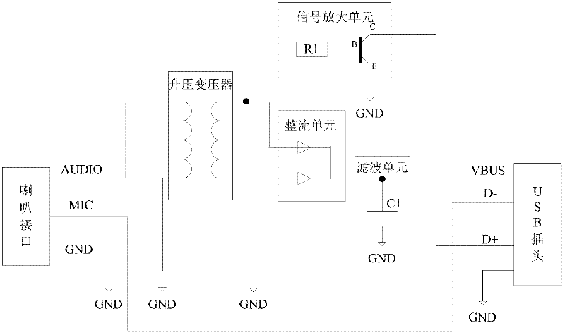
[0132] Figure 4 It is a schematic structural diagram of the third embodiment of the audio signal switching device of the present invention; Figure 4 As shown, the difference between the third embodiment of the audio signal switching device and the first embodiment is:

[0133] In the third embodiment of the audio signal conversion device, only one output pin in the secondary coil of the step-up transformer is connected with the input pin of the rectification unit, so the rectification unit only needs to include one input pin, and only one input pin is needed in the rectification unit. A diode is included.

[0134] Obviously, compared with the first embodiment, this embodiment will lose half of the electric energy of the secondary coil of the step-up transformer, but the circuit structure can be simplified and the hardware cost can be reduced.

[0135] In this embodiment, another output pin of the secondary coil of the step-up transformer is grounded, and the step-up transf...


PUM


Abstract

The invention discloses an audio signal receiving and transferring device. The audio signal transferring device comprises an input interface and a USB (Universal Serial Bus) output interface; the audio signal transferring device further comprises a boosting unit, a rectification unit and a filtering unit, wherein the input interface further comprises a first audio signal input pin used for receiving an audio signal sent by an audio signal sending device connected with the pin and outputting the obtained audio signal to an input end of the boosting unit; the boosting unit is used for boosting the audio signal input by the input end and outputting the boosted audio signal to the input end of the rectification unit through an output end of the rectification unit; the rectification unit is used for rectifying the boosted audio signal input by the input end and outputting the rectified electrical level to the input end of the filtering unit through the output end of the filtering unit; and the filtering unit is used for filtering the electrical level input by the input end and outputting the filtered direct current electrical level to a VBUS (Voltage Bus) pin of the USB output interface through the output end.

Description

technical field [0001] The invention relates to the field of electronic technology, in particular to an audio signal receiving device and an audio signal switching device. Background technique [0002] With the development of audio signal encoding / decoding technology, more and more electronic devices transmit data through audio interfaces. For example, the electronic device may be connected to the mobile communication device through a low-impedance voice coil speaker interface (eg, earphone jack) of the mobile communication device (eg, a mobile phone), and receive audio signals output by the mobile communication device. [0003] Since the output power of the low-impedance voice coil speaker interface is very small, except for electronic devices with low power consumption (such as headphones), electronic devices that receive audio signals through the low-impedance voice coil speaker interface usually need to use an external power supply or a built-in Only the battery can wor...

Claims


Application Information

Patent Timeline
IPC IPC(8): H01R31/06H01R13/66H01R13/719H04R3/00
CPCH04R5/04H04R2420/09H03F3/181
Inventor 李东声
Owner TENDYRON CORP
Why Eureka
Try Eureka