
Composite paved deformation joint structure

A deformation joint and structure technology, applied in pavement details, bridge parts, roads, etc., can solve problems such as large shear force, material fatigue damage, and difficulty in adapting to shear misalignment deformation, and achieves reduction of impact noise, good deformation coordination, Simple and convenient construction

Inactive Publication Date: 2013-11-06
CHONGQING JIAOTONG UNIVERSITY
View PDF5 Cites 0 Cited by
  • Summary
  • Abstract
  • Description
  • Claims
  • Application Information

AI Technical Summary

Problems solved by technology

The advantage of rigid joints is that it can provide a relatively smooth working surface. The disadvantage is that it is difficult to adapt to the shearing deformation between adjacent structures due to poor foundation settlement, poor creep deformation of structural concrete, and poor rotation angle at the end of the structure. The seam is easy to generate a large shear force, which often causes damage to the seam material
Although flexible joints can well adapt to the relative expansion and shearing deformation of adjacent structures at the joints, it is easy to cause discontinuous conditions on the working surface at the joints, which affects the use of the structure; in addition, the expansion joints are also prone to live The impact of the load causes loud noise and the material is prone to fatigue damage

Method used


Image

  • Composite paved deformation joint structure

Examples


Embodiment Construction

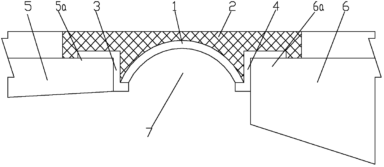
[0019] figure 1 It is a schematic diagram of the structure of the present invention, as shown in the figure: the composite pavement deformation joint structure of the present embodiment is especially suitable for road and bridge construction; Correspondingly fixed at the ends of the two structures forming the deformation joints, as shown in the figure, the two structures forming the deformation joints are structure 5 and structure 6 respectively, one arch foot of the arched plate 1 is supported on the structure 5, and the arched plate 1 The other arch foot is supported on the structure 6; the vault of the arched plate 1 is lower than the upper working surfaces of the two structures forming the deformation joints, and the flexible pavement 2 is paved on the arched plate 1 to cover the deformation joints 7 and forms The upper working surfaces of the two structures (structure 5 and structure 6) of the deformation joint are even, and the flexible pavement layer 2 adopts a similar ...


PUM


Abstract

The invention discloses a composite paved deformation joint structure which comprises an arched plate and a flexible pavement layer, wherein two arch pins of the arched plate are correspondingly and fixedly arranged to two structure ends of a deformation joint respectively; the arch top of the arched plate is lower than the upper working surfaces of two structures for forming the deformation joint; and the flexible pavement layer is paved on the arched plate for covering the deformation joint and is parallel and level to the upper working surfaces of the two structures for forming the deformation joint. The composite paved deformation joint structure can effectively bear the vertical workload applied by the surface of the deformation joint, be more favorably adapted to the vertical displacement difference and the horizontal relative displacement of the adjacent structure at the joint and provide a smooth and continuous working surface, and therefore, the composite paved deformation joint structure can not suffer obvious movement load impact, reduces impact noise and the probability of generating fatigue damage, can synthesize the advantages of a rigid joint and flexible joint scheme, form a smooth and continuous working surface on the deformation joint and provide enough deformation amount, has high deformation harmony, prevents damage caused under larger shearing force and has the advantages of simple and convenient construction, long service life and low maintenance cost.

Description

technical field [0001] The invention relates to an auxiliary structure in the field of civil engineering, in particular to a structure for deformation joints of pavement structures. Background technique [0002] Deformation joints are used in the field of civil engineering to prevent roads and bridges and other buildings from deforming under the action of various factors (temperature changes, creep deformation, uneven foundation settlement and earthquakes), resulting in cracking or even destruction. The gaps of appropriate width are artificially set. [0003] Deformation joints are located between adjacent structures, especially in the construction of roads and bridges, the joint technology of deformation joints between adjacent structures is widely used. In the prior art, commonly used joint forms mainly include: rigid joints formed by reinforced concrete, steel-concrete or steel parts; and flexible joints formed by factory-finished expansion joints. The advantage of rigid...

Claims


Application Information

Patent Timeline
Patent Type & Authority Patents(China)
IPC IPC(8): E01C11/02E01D19/06
Inventor 彭凯陈东军魏文财徐基平程浩
Owner CHONGQING JIAOTONG UNIVERSITY
Learn More