Light reflecting cup of light-emitting diode (LED) lamp bank

A technology of LED lamps and reflectors, applied in the direction of light sources, reflectors, point light sources, etc., can solve the problems of difficult light control of reflectors, large light spots, and light that cannot shine on work and living surfaces, etc., to achieve Improve the effective utilization rate, simple structure, and reduce the effect of spot

Inactive Publication Date: 2013-12-25
TIANTAI TIANYU OPTOELECTRONIC CO LTD
View PDF4 Cites 0 Cited by
  • Summary
  • Abstract
  • Description
  • Claims
  • Application Information

AI Technical Summary

Problems solved by technology

[0002] At present, during the use of some lamps, especially LED lamps, the light emitted by the light source that cannot be illuminated on the work and living surfaces is reflected by the secondary light distribution technology of the existing reflector cup, which can greatly improve the light emission of the lamp. The utilization rate of the lamps greatly improves the working efficiency of the lamps, but the existing reflectors are relatively difficult to control the light. Generally, there is a reflective plane on the inside of the reflectors, which is difficult to achieve the actual lighting distribution requirements and the effective use of the total luminous flux of the lamps. The efficiency is not high enough, the formed spot is large, and the lighting effect is not ideal

Method used


Image

  • Light reflecting cup of light-emitting diode (LED) lamp bank
  • Light reflecting cup of light-emitting diode (LED) lamp bank
  • Light reflecting cup of light-emitting diode (LED) lamp bank

Examples


Embodiment Construction

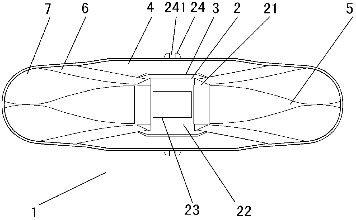
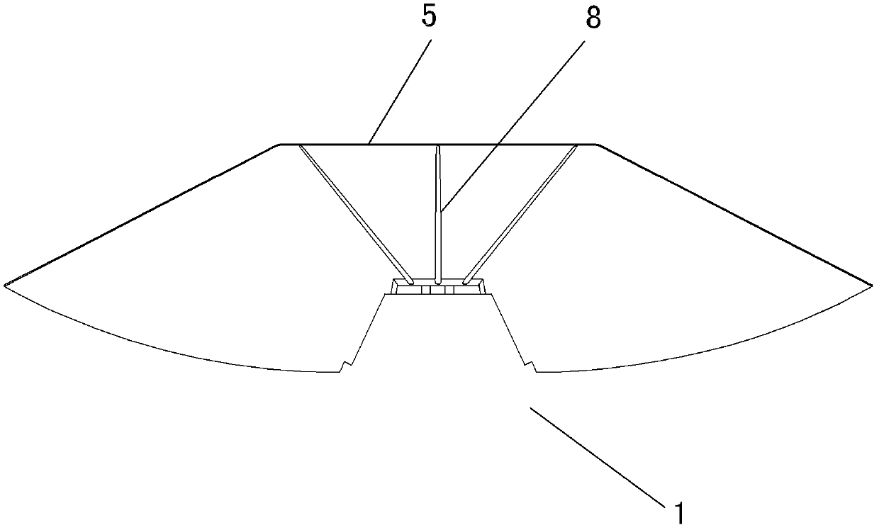
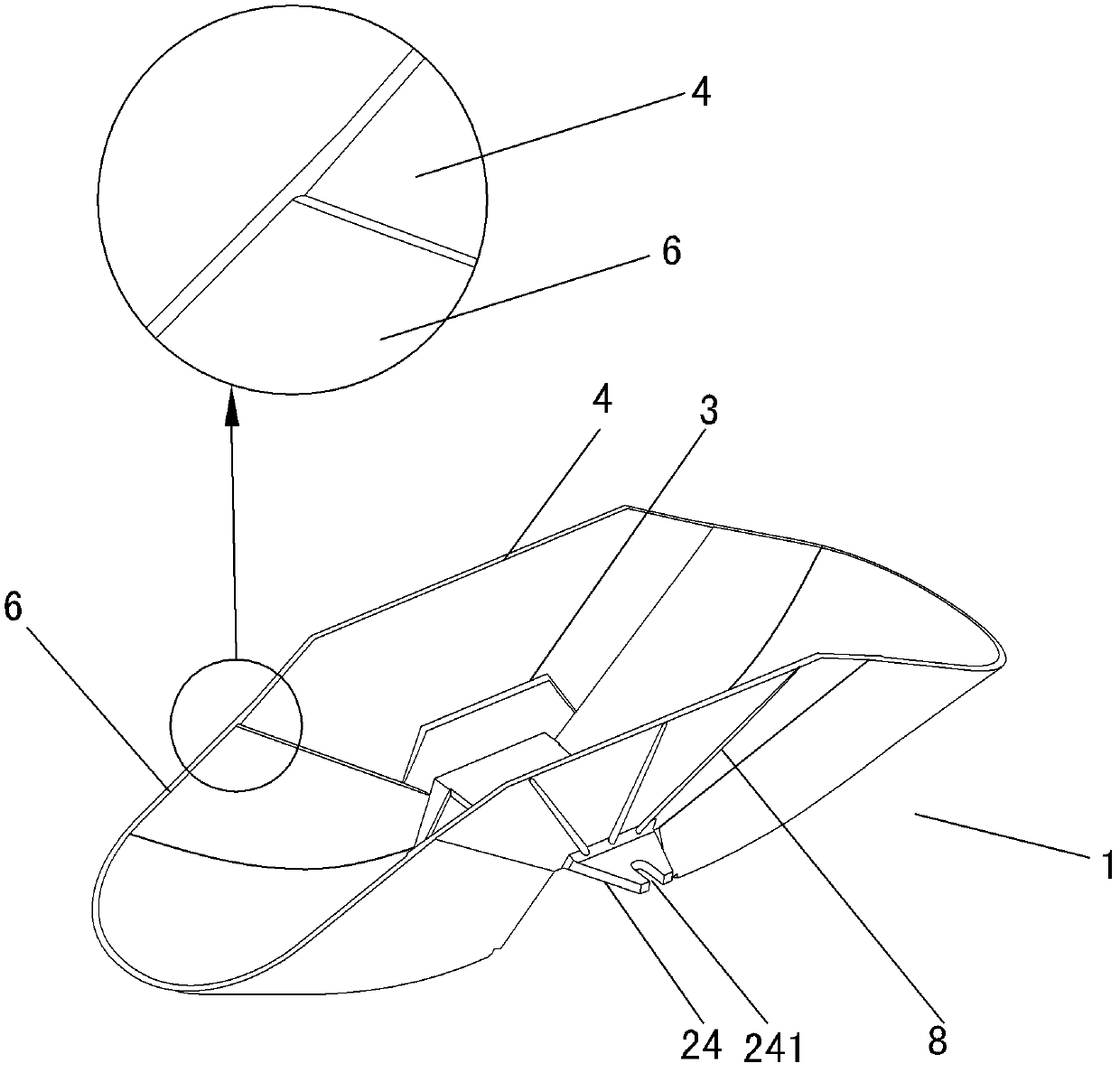
[0027] Below in conjunction with accompanying drawing, the present invention will be further described with specific embodiment, see Figure 1-8 : A reflective cup 1 for an LED lamp group, the front and rear sides of the lamp group mounting seat 2 arranged longitudinally are symmetrically provided with a primary reflective surface 3 upward, the primary reflective surface 3 on the front side is forward, and the primary reflective surface 3 on the rear side is respectively backward A secondary reflective surface 4 is provided, and a secondary parabolic surface 5 is symmetrically arranged on the left and right sides of the lamp group mounting base 2, the front side of the secondary reflective surface 4 on the front side, and the rear side of the secondary reflective surface 4 on the rear side Reflecting planes 6 are respectively arranged on the left and right sides, and the circular arc surface 7 is used for a smooth transition between the front and rear reflecting planes 6 on the...


PUM


Abstract

The invention belongs to the technical field of lighting products, and provides a light reflecting cup of an LED (light-emitting diode) lamp bank. Primary reflecting surfaces and secondary reflecting surfaces are arranged upwards on the front side and the back side of a longitudinally-arranged lamp bank mounting seat symmetrically; secondary parabolic surfaces are symmetrically arranged on the left side and the right side of the bottom of the lamp bank mounting seat; reflecting flat surfaces are respectively leftwards and rightwards arranged on the secondary reflecting surfaces on the front side and the back side of the lamp bank mounting seat and in smooth transition with the secondary parabolic surfaces by using circular arc surfaces; LED lamp mounting holes are formed a left inclined surface, a right inclined surface and an upper bottom surface of the lamp bank mounting seat; mounting and connecting lugs respectively extend frontwards and backwards from the front side and the back side of the upper bottom surface; a mounting hole is formed on each mounting and connecting lug; and the reflecting cup is integrally formed in a ship shape or a shoe-shaped ingot shape. Due to the structural characteristics, the light reflecting cup has the advantages of simple structure, small formed light spot, high light source utilization rate, low cost, and the like.

Description

technical field [0001] The invention belongs to the technical field of lighting products, in particular to a reflective cup for an LED lamp group. Background technique [0002] At present, during the use of some lamps, especially LED lamps, the light emitted by the light source that cannot be illuminated on the work and living surfaces is reflected by the secondary light distribution technology of the existing reflector cup, which can greatly improve the light emission of the lamp. The utilization rate of the lamps greatly improves the working efficiency of the lamps, but the existing reflectors are relatively difficult to control the light. Generally, there is a reflective plane on the inside of the reflectors, which is difficult to achieve the actual lighting distribution requirements and the effective use of the total luminous flux of the lamps. The efficiency is not high enough, the formed spot is large, and the lighting effect is not ideal. Contents of the invention ...

Claims


Application Information

Patent Timeline
Patent Type & Authority Patents(China)
IPC IPC(8): F21V7/06F21V7/10F21Y101/02
Inventor 陈海洋卢祖米
Owner TIANTAI TIANYU OPTOELECTRONIC CO LTD
Why Eureka
Try Eureka