Display

A display and slit technology, applied in the display field, can solve the problems such as the reduction of the aperture ratio of the electrowetting display, the increase of the complexity of the driving system design, and the increase of the response time.

Inactive Publication Date: 2012-03-21
IND TECH RES INST
View PDF3 Cites 5 Cited by
  • Summary
  • Abstract
  • Description
  • Claims
  • Application Information

AI Technical Summary

Problems solved by technology

Please refer to Figure 2A to Figure 2E , it is worth noting that when the electrowetting display pixel structure is driven at an increased voltage in order to speed up the reaction speed, the configuration of these patterned pixel electrodes PE may cause the non-polar fluid 134 (indicated by a uniform point in the figure) to be in the Splitting occurs during contraction (eg Figure 2D As shown in the broken shape), after a period of time, it gradually shrinks back to the electrodeless region 116 of the electrowetting display pixel structure. The splitting process of the non-polar fluid 134 tends to reduce the aperture ratio of the electrowetting display, increase the response time, Increased complexity of drive system design and reduced display quality

Method used


Image

  • Display
  • Display
  • Display

Examples


Embodiment Construction

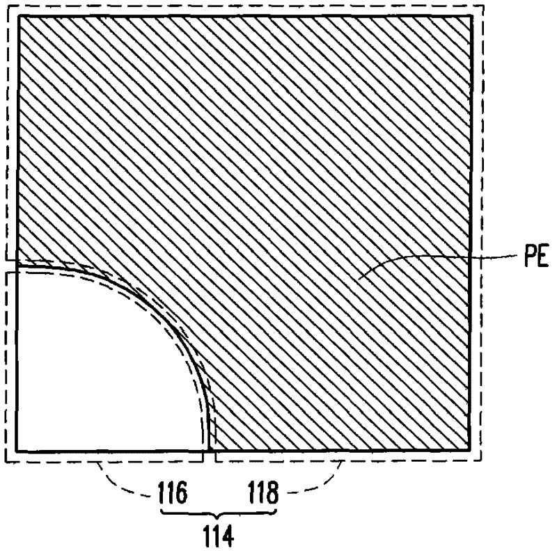
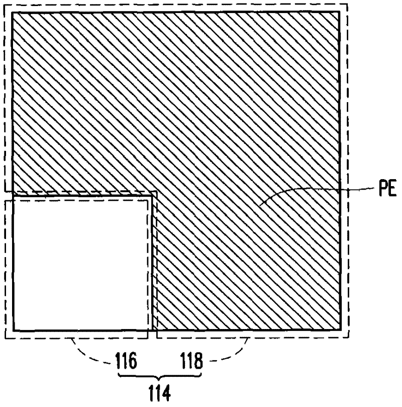
[0045] image 3 It is a partial top view cross-sectional schematic diagram of a display according to an embodiment of the present invention. Please refer to image 3 , the display 100 of this embodiment includes a pixel matrix substrate 110 , a pair of facing substrates 120 and a flow medium 130 . The pixel matrix substrate 110 includes a first substrate 112 and a plurality of pixel structures 200 . The pixel structures 200 are, for example, arranged in a matrix on the first substrate 112 .

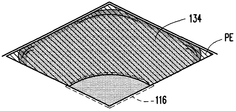
[0046] In this embodiment, the opposite substrate 120 includes a second substrate 122 and a common electrode 124 , wherein the common electrode 124 is located on the second substrate 122 . The flow medium 130 includes a polar fluid 132 and a non-polar fluid 134 (in Figure 4A to Figure 4D represented by uniform dense dots), flows between the pixel matrix substrate 110 and the opposite substrate 120 , and the polar fluid 132 and the non-polar fluid 134 are not miscible with each other....


PUM


Abstract

A display including a pixel array substrate, an opposite substrate and a fluid medium is provided. The pixel array substrate includes a first substrate including pixel regions and pixel structures disposed in the pixel regions. Each pixel region includes a distribution region of pixel electrode and a non-electrode region. A pixel electrode of the pixel structure is disposed in the distribution region of pixel electrode and has at least one slit extending from the non-electrode region toward the distribution region of pixel electrode. The opposite substrate includes a second substrate and a common electrode disposed on the second substrate and contacting a polar fluid. The fluid medium includes the polar fluid and a non-polar fluid and flows between the pixel array substrate and the opposite substrate. The non-polar fluid is contracted toward the non-electrode region when a voltage difference is generated between the pixel and the common electrodes.

Description

technical field [0001] The invention relates to the display field, in particular to a display. Background technique [0002] An electrowetting display includes a plurality of electrowetting display pixel structures, wherein each electrowetting display pixel structure may include barrier walls, pixel electrodes, insulating layers, hydrophobic layers, polar fluids, and nonpolar fluids. The insulating layer is arranged on the surface of the pixel electrode, and the hydrophobic layer covers the insulating layer. The non-polar fluid is arranged on the surface of the hydrophobic layer, the polar fluid covers the non-polar fluid, and the barrier wall is arranged on the hydrophobic layer to separate two adjacent pixel structures. [0003] When each electrowetting display pixel structure is in a state where a voltage is applied, the polar fluid is driven by electrostatic force to bring the polar fluid into affinity contact with the electrode, and push the non-polar fluid to the corr...

Claims


Application Information

Patent Timeline
Patent Type & Authority Applications(China)
IPC IPC(8): G02B26/02
CPCG02B26/005
Inventor 古昀生罗国隆郑惟元蔡宇翔陈庆耀黄裕盛
Owner IND TECH RES INST
Why Eureka
Try Eureka