
Communication cavity device and combining and distribution structure thereof

A technology of combining, splitting, and cavity, which is applied in the field of communication cavity devices, can solve problems such as inability to adapt to the market environment and limited application range

Active Publication Date: 2013-11-20
COMBA TELECOM TECH (GUANGZHOU) CO LTD +1
View PDF1 Cites 0 Cited by
  • Summary
  • Abstract
  • Description
  • Claims
  • Application Information

AI Technical Summary

Problems solved by technology

In the technical solution disclosed in this patent application, a band-stop filter is used to realize a broadband low-frequency signal channel. The relative bandwidth of this low-frequency signal channel can reach 200%, but its limitation is that the band-stop filter has a It is difficult to achieve sufficient rejection in a wide frequency band, so the other signal channel can only be realized by a narrowband filter to ensure sufficient passband isolation between the two channels
Therefore, the application range of this combiner is limited and cannot adapt to the new market environment
[0004] The combination of two channels with high relative bandwidth requires skill to ensure the interference-free combination of the signals of the two channels. Although the combination and splitting structure of the known combiner can meet this requirement to some extent, But it may not be able to obtain better technical indicators

Method used


Image

  • Communication cavity device and combining and distribution structure thereof
  • Communication cavity device and combining and distribution structure thereof
  • Communication cavity device and combining and distribution structure thereof

Examples


Embodiment Construction

[0042] Below in conjunction with accompanying drawing and embodiment the present invention will be further described:

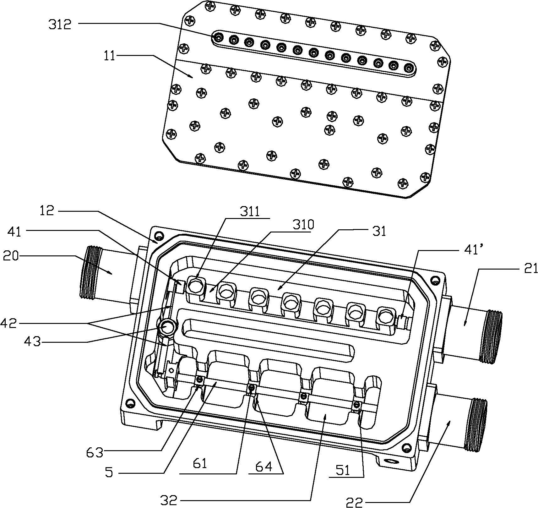
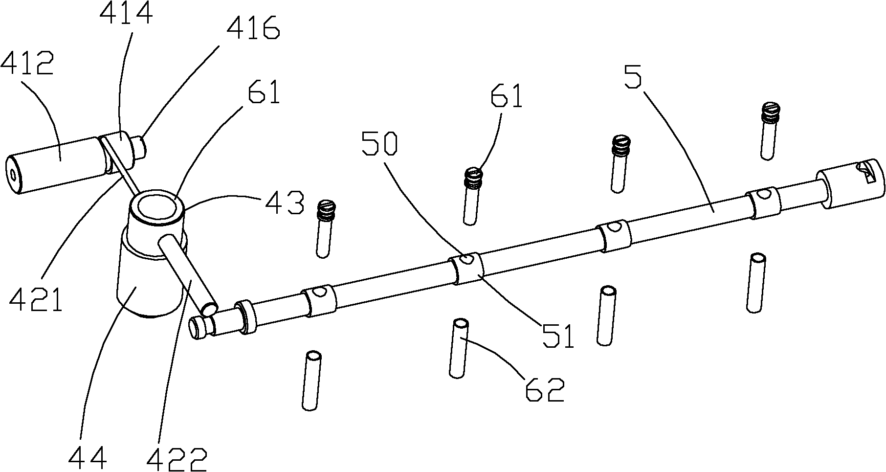
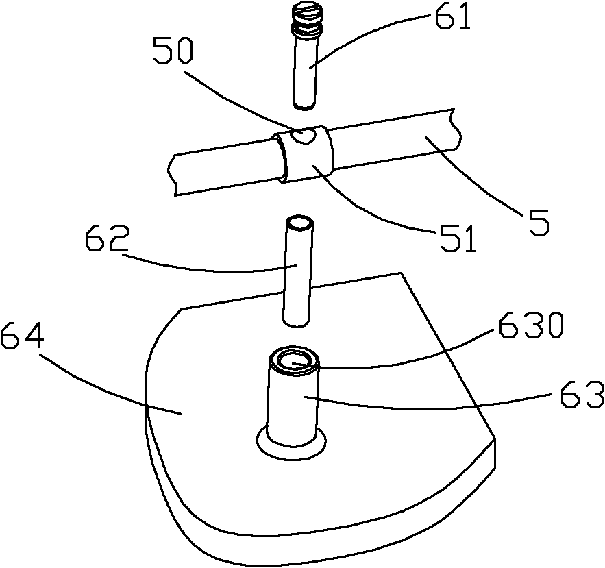
[0043] see figure 1, a general cavity device disclosed in a preferred embodiment of the present invention is a combiner for combining and demultiplexing signals of two different frequency bands. The main body of the combiner is a cavity 12, and a cover plate 11 is installed above the cavity 12, so that the combiner as a whole forms a cavity device. The cavity 12 is provided with two signal channels 31, 32, wherein the first signal channel 31 is a band-pass filter channel for filtering the first frequency band signal; the second signal channel 32 is a low-pass filter channel for for filtering the second frequency band signal. The first frequency band is a relatively higher frequency band, and the second frequency band is a relatively lower frequency band, and each frequency band may include one or more sub-frequency bands belonging to independent communicati...


PUM


Abstract

Disclosed are a communication cavity component and a path-combining / splitting structure thereof. The path-combining / splitting structure comprises: a connector, where one end thereof forms a public port, while the other end is used for coupling a first frequency band signal of the communication cavity component, an impedance transformation transmission cable, where one end thereof is used for accessing a second frequency band signal of the communication cavity component, while the other end is connected to the connector, and comprises at least two cable segments having different impedances, a resonant column serial-connected to the mid-section of the impedance transformation transmission cable, and a medium support element used for fixing the resonant column and for insulating the resonant column from the communication cavity component. The present invention uses the path-combining / splitting structure to allow the two frequency band signals to implement great isolation and thereby to perform path-combination and path-splitting, and, by merging an elliptic function-type low-pass filter having a unique structure, allows to generate enhanced out-of-band rejection under the premise of ensuring a relatively high bandwidth, thus meeting a requirement for increased isolation between communication systems.

Description

【Technical field】 [0001] The invention relates to a communication cavity device for combining multiple communication signals, which is suitable for cavity devices such as combiners, duplexers, and filters, and specifically relates to a communication cavity device used in the communication cavity device. A combination and branch structure. 【Background technique】 [0002] With the development of triple play integration and the use of LTE frequency bands, compared with traditional frequency bands, new frequency bands are moving towards lower and higher directions. With the introduction of new standards or systems, the market has higher and higher requirements for combiners, hoping to realize the combination and splitting of wider frequency band signals. However, for such a wide-band combiner, the traditional implementation method can no longer meet the requirements, and a new implementation method needs to be introduced. [0003] The patent application with publication number...

Claims


Application Information

Patent Timeline
Patent Type & Authority Patents(China)
IPC IPC(8): H01P1/20H01P1/207H01P1/208H01P1/213
CPCH01P1/2138
Inventor 郭春波邸英杰党志南昌敏华
Owner COMBA TELECOM TECH (GUANGZHOU) CO LTD
Learn More