Annular voltage-controlled oscillator

A voltage-controlled oscillator and ring technology, applied in power oscillators, electrical components, etc., can solve problems such as large temperature and process effects

Active Publication Date: 2012-03-21
UNIV OF ELECTRONIC SCI & TECH OF CHINA
View PDF4 Cites 32 Cited by
  • Summary
  • Abstract
  • Description
  • Claims
  • Application Information

AI Technical Summary

Problems solved by technology

[0009] The purpose of the present invention is to solve the problem that the existing oscillator circ

Method used


Image

  • Annular voltage-controlled oscillator
  • Annular voltage-controlled oscillator
  • Annular voltage-controlled oscillator

Examples


Embodiment Construction

[0017] The present invention will be described in detail below in conjunction with the accompanying drawings and embodiments.

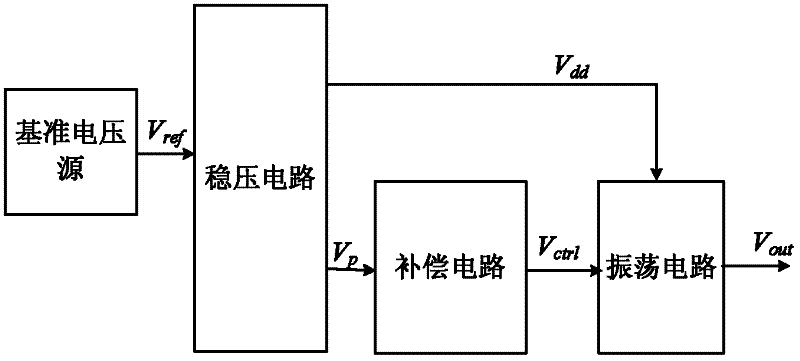
[0018] The structural block diagram of the ring voltage controlled oscillator proposed by the present invention is as follows: figure 1 As shown, it specifically includes a reference voltage source, a voltage regulator circuit, a compensation circuit and an oscillation circuit. The output of the reference voltage source is connected to the input terminal of the voltage stabilizing circuit; the voltage stabilizing circuit amplifies the reference voltage in proportion to generate two output voltages, the first output is used as the operating voltage of the oscillation circuit, and the second output is input to the compensation circuit as the input voltage of the compensation circuit; the output terminal of the compensation circuit is connected to the oscillation circuit, the output of the compensation circuit is used as the bias voltage of the oscillati...


PUM


Abstract

The invention discloses an annular voltage-controlled oscillator, which comprises a reference voltage source, a voltage stabilizing circuit, a compensation circuit and an oscillation circuit; the output of the reference voltage source is connected with the input end of the voltage stabilizing circuit; the voltage stabilizing circuit generates two output voltages, and the first output is used as a working voltage of the oscillation circuit while the second output is input to the compensation circuit as an input voltage of the compensation circuit; and the output of the compensation circuit is used as a bias voltage of the oscillation circuit. The oscillator controls the oscillation frequency of the oscillation circuit by generating a bias voltage changed along the temperature and the technology to realize automatic compensation of output frequency deviation of the oscillator. When temperature rise results in frequency increment of the oscillation circuit, the compensation circuit generates a control voltage reduced along the temperature so as to compensate drop of frequency; and when a process corner is changed from SS (Slow nmos and Slow pmos) to FF (Fast nmos and Fast pmos), the oscillation circuit also has a rise and the compensation circuit generates a control voltage reduced along the technology so as to compensate drop of frequency.

Description

technical field [0001] The invention belongs to the technical field of integrated circuit design, and in particular relates to a ring voltage-controlled oscillator with temperature and process self-compensation functions. Background technique [0002] Oscillators are a major building block of many electronic systems, with applications ranging from clock generation in microprocessors to carrier synthesis in wireless communication systems. The most common oscillator is the quartz crystal oscillator. The performance of the crystal oscillator is very stable and the precision is very high, but it cannot be integrated inside the chip system. Using the standard CMOS process to realize the on-chip oscillator to replace the off-chip crystal oscillator will be very helpful for reducing the cost of the system and improving the integration of the system. [0003] With the development of semiconductor process technology, the integration of chips is getting higher and higher, which leads...

Claims


Application Information

Patent Timeline
IPC IPC(8): H03B5/04
Inventor 文光俊王耀刘佳欣
Owner UNIV OF ELECTRONIC SCI & TECH OF CHINA
Why Eureka
Try Eureka