
PON (passive optical network) network fault detection method and device

A network fault and network technology, applied in the direction of selecting devices, transmission monitoring/testing/fault measurement systems, fault recovery arrangements, etc., can solve the problems of slow positioning speed and low efficiency, and achieve the effect of low cost

Active Publication Date: 2012-03-21
CHINA TELECOM CORP LTD
View PDF5 Cites 33 Cited by
  • Summary
  • Abstract
  • Description
  • Claims
  • Application Information

AI Technical Summary

Problems solved by technology

Obstacle detection and positioning are slow and inefficient

Method used


Image

  • PON (passive optical network) network fault detection method and device
  • PON (passive optical network) network fault detection method and device
  • PON (passive optical network) network fault detection method and device

Examples


Embodiment Construction

[0033] Various exemplary embodiments of the present invention will now be described in detail with reference to the accompanying drawings. It should be noted that the relative arrangements of components and steps, numerical expressions and numerical values ​​set forth in these embodiments do not limit the scope of the present invention unless specifically stated otherwise.

[0034] At the same time, it should be understood that, for the convenience of description, the sizes of the various parts shown in the drawings are not drawn according to the actual proportional relationship.

[0035] The following description of at least one exemplary embodiment is merely illustrative in nature and in no way taken as any limitation of the invention, its application or uses.

[0036] Techniques, methods and devices known to those of ordinary skill in the relevant art may not be discussed in detail, but where appropriate, such techniques, methods and devices should be considered part of the...


PUM


Abstract

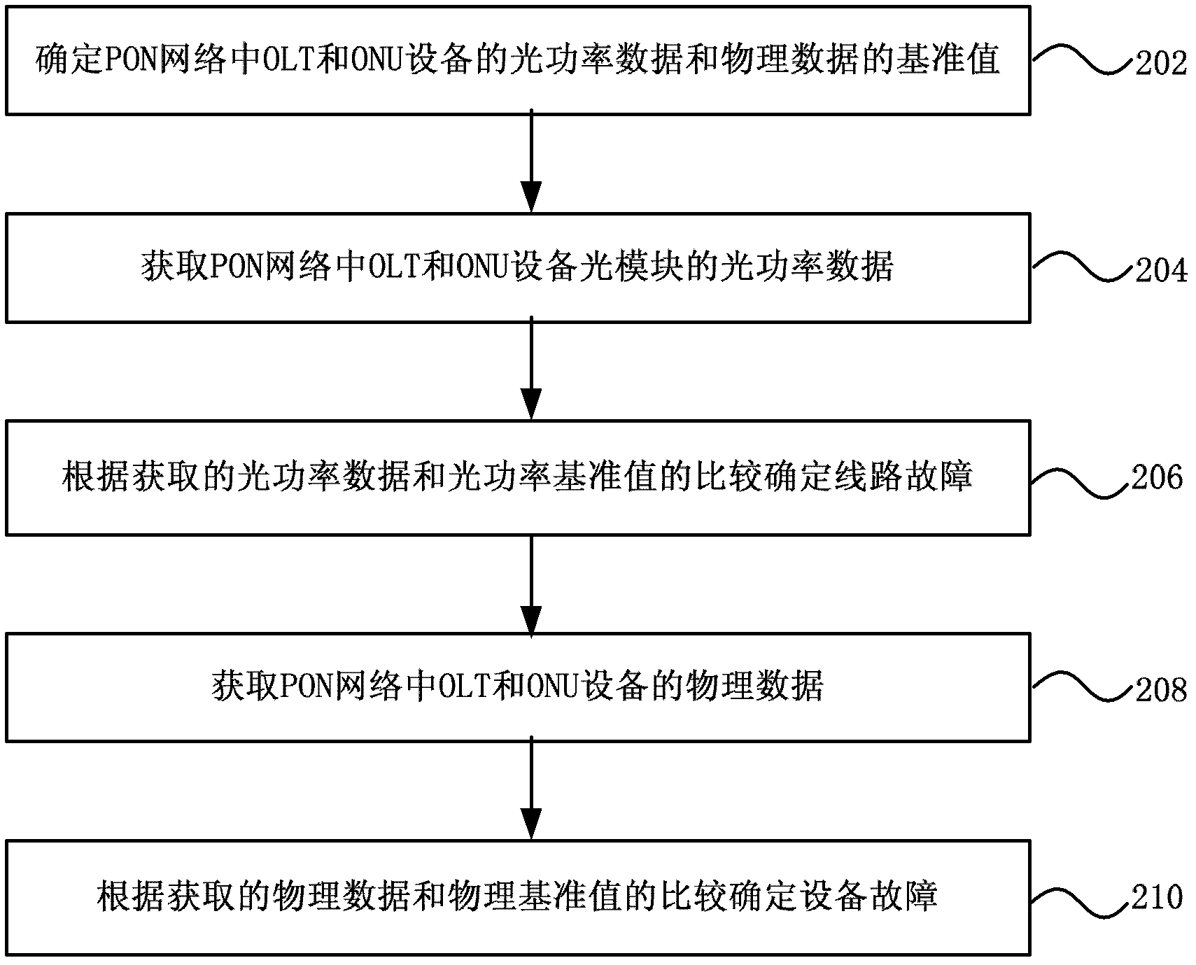
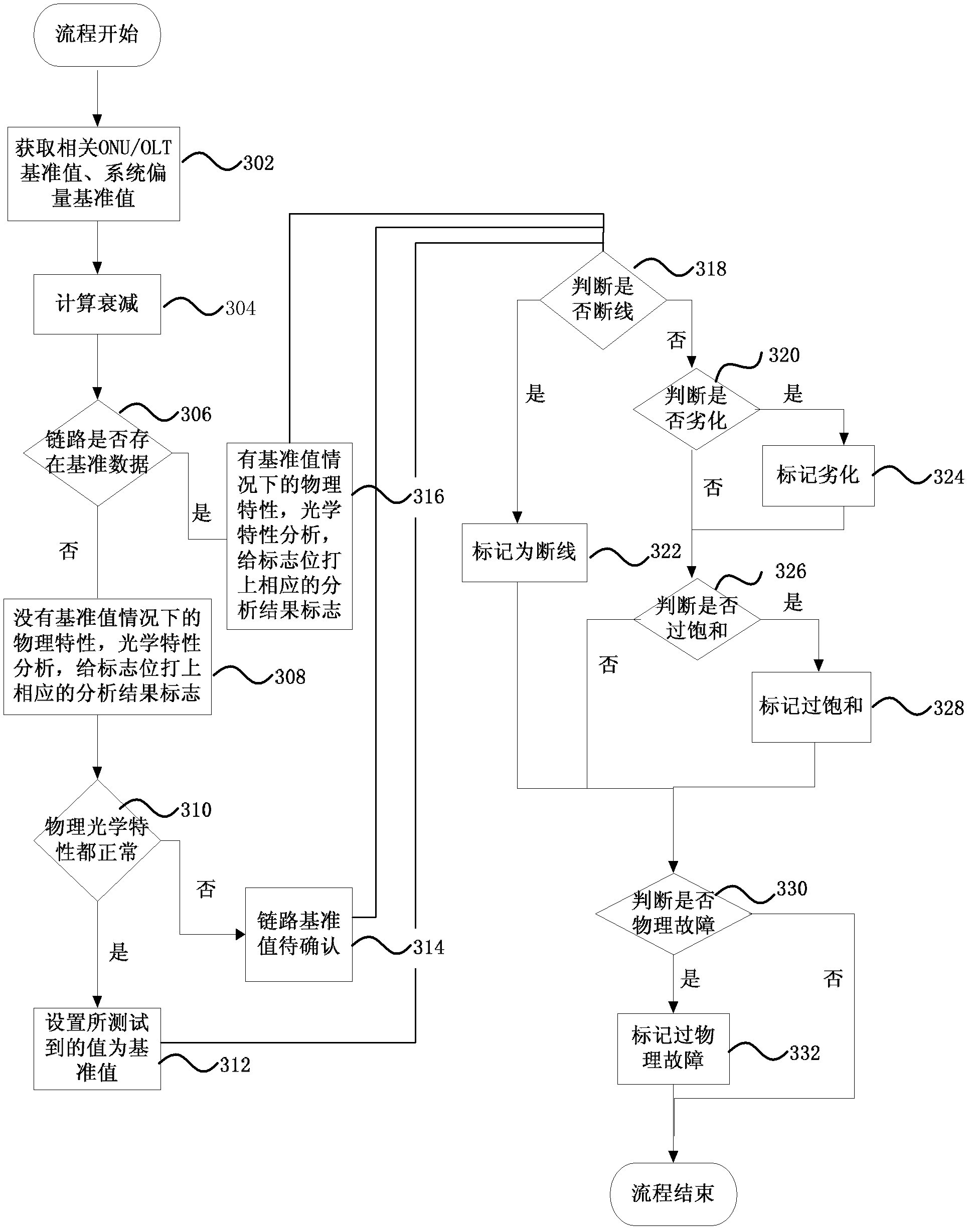
The invention discloses a technical scheme for PON (passive optical network) network fault detection and positioning and relates to a PON technology. The method comprises the following steps: acquiring data of optical modules of OLT (optical line terminal) and ONU (optical network unit) equipment in a PON; and determining a PON network fault by comparing the acquired data of the optical modules with reference values. The method is greatly different from the existing fault detection way, the way does not need to transform a circuit, an external testing device is not required, the cost is low, the method can be applied to the current network, and the positioning is accurate.

Description

technical field [0001] The present invention relates to PON (Passive Optical Network, passive optical network) network technology, in particular to a PON network fault detection method and device. Background technique [0002] After a fault occurs in traditional copper cable access, the fault location and repair technologies are relatively mature, while the PON network is still in the stage of vigorous development and construction, and the technology for fault detection and location is not mature. [0003] In the prior art, there is a method of detecting and locating obstacles in a PON network through an OTDR (Optical Time Domain Reflectometer, Optical Time Domain Reflectometer) test, but it encounters many problems in the application of the PON network. Due to the 1:N topology of the PON network, when the OTDR sends the test wave from the local end to the user end, the scope of obstacle location is limited to the backbone and cannot penetrate the optical branch. The reason ...

Claims


Application Information

Patent Timeline
IPC IPC(8): H04B10/08H04B10/12H04Q11/00H04B10/03H04B10/07H04L12/24
Inventor 张军张永生汪国荣章荐章伟黄金晶
Owner CHINA TELECOM CORP LTD
Learn More