Leg mechanism for four-legged robots
A technology of quadruped robot and leg mechanism, which is applied in motor vehicles, transportation and packaging, etc., can solve the problems of quadruped robot research that has a large impact and less physical production, so as to reduce control difficulty, improve motion performance, design compact effect
- Summary
- Abstract
- Description
- Claims
- Application Information
AI Technical Summary
Problems solved by technology
Method used
Image
Examples
Embodiment 1
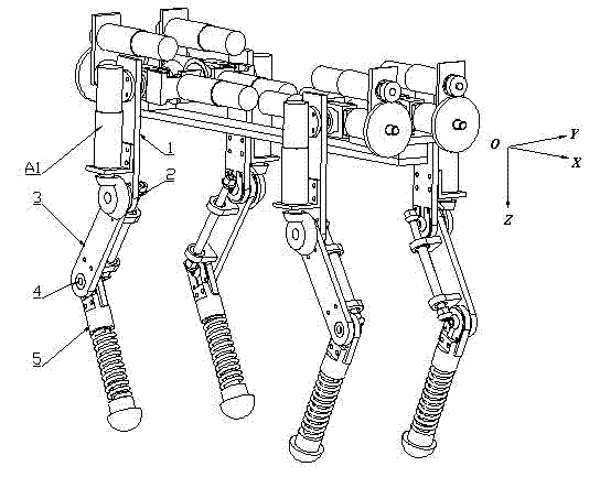
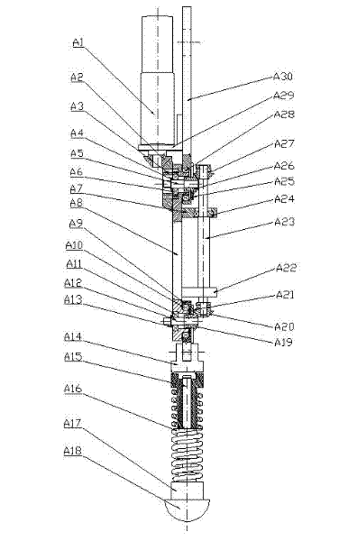
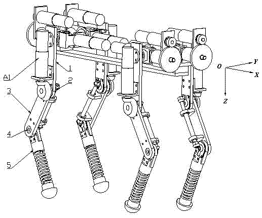
[0028] see figure 2 , the leg mechanism of this quadruped robot includes the drive motor (A1), the femoral mechanism (1), the knee hinge (2), the tibial mechanism (3), the bare joint hinge (4) and the metatarsal mechanism (5):
[0029] 1) The femoral mechanism (1) is hinged to the tibial mechanism (3) through the knee hinge (2).
[0030] 2) The driving motor (A1) is fixedly installed on the femoral mechanism (1), and the output shaft of the driving motor drives the tibial mechanism (3) to rotate through the bevel gear transmission mechanism in the knee hinge (2).
[0031] 3) The tibial mechanism (3) is hinged to the metatarsal mechanism (5) through the bare joint hinge (4).
[0032]4) The driving motor (A1) drives the metatarsal mechanism (5) through the bevel gear transmission mechanism in the knee joint hinge (2) and the bevel gear transmission mechanism in the bare joint hinge (4).
Embodiment 2
[0034] This embodiment is basically the same as Embodiment 1, and the features are as follows:
[0035] The femoral mechanism (1) includes a femoral connecting rod (A30) and a motor fixing bracket (A29), the motor fixing bracket (A29) is fixed on the femoral connecting rod (A30) through bolts, and the driving motor (A1) is fixedly installed on the motor fixing bracket (A29). Make sure that the output shaft of the drive motor (A1) is installed axially along the femoral rod (A30) on the bracket (A29).
[0036] The tibial mechanism (3) includes a tibial connecting rod (A8), a tibial transmission shaft (A23), an upper bearing seat (A7) and a lower bearing seat (A22), and the upper bearing seat (A7) and the lower bearing seat (A22) are respectively It is fixed on the tibial connecting rod (A8) by bolts, and the tibial transmission shaft (A23) is installed parallel to the tibial connecting rod (A8) through the support of the bearings (A24) in the upper and lower bearing seats (A7, A...
PUM
 Abstract
Description
Claims
Application Information
 - R&D
- Intellectual Property
- Life Sciences
- Materials
- Tech Scout
- Unparalleled Data Quality
- Higher Quality Content
- 60% Fewer Hallucinations
Browse by: Latest US Patents, China's latest patents, Technical Efficacy Thesaurus, Application Domain, Technology Topic, Popular Technical Reports.
© 2025 PatSnap. All rights reserved.Legal|Privacy policy|Modern Slavery Act Transparency Statement|Sitemap|About US| Contact US: help@patsnap.com


