Measuring cup type metering mechanism without bin gate

A measuring cup and material gate technology, which is applied in the field of the measuring cup type measuring mechanism without material gate, can solve the problems such as difficulty in grasping the flatness of the upper turntable 4 and the lower turntable 5, wear of the metal surface, and increase of electric power of the motor, so as to save the cleaning workload, The effect of reducing material waste and strong operability

Active Publication Date: 2012-03-28
珠海瑞创科技发展有限公司
View PDF8 Cites 20 Cited by
  • Summary
  • Abstract
  • Description
  • Claims
  • Application Information

AI Technical Summary

Problems solved by technology

[0003] Using this metering mechanism, since the material falls into the upper and lower measuring cups (3, 3') by its own gravity, when the upper and lower rotating disks 4 and 5 drive the upper and lower measuring cups (3, 3') to rotate together, they will be squeezed first. Press out excess material on the upper turntable 4, resulting in material waste. At the same time, when the material door 6 is forced to open after hitting the limit post, the material door 6 will contact with the material to generate a friction force to force the material to be thrown forward, causing the material Waste; secondly, in order to meet the size requirements of the material door 6 and the upper and lower measuring cups (3, 3 '), the mechanism must adopt a large manufacturing size of the upper turntable 4 and the lower turntable 5, which virtually causes the entire upper turntable 4 The flatness of the upper and lower turn

Method used


Image

  • Measuring cup type metering mechanism without bin gate
  • Measuring cup type metering mechanism without bin gate
  • Measuring cup type metering mechanism without bin gate

Examples


Embodiment Construction

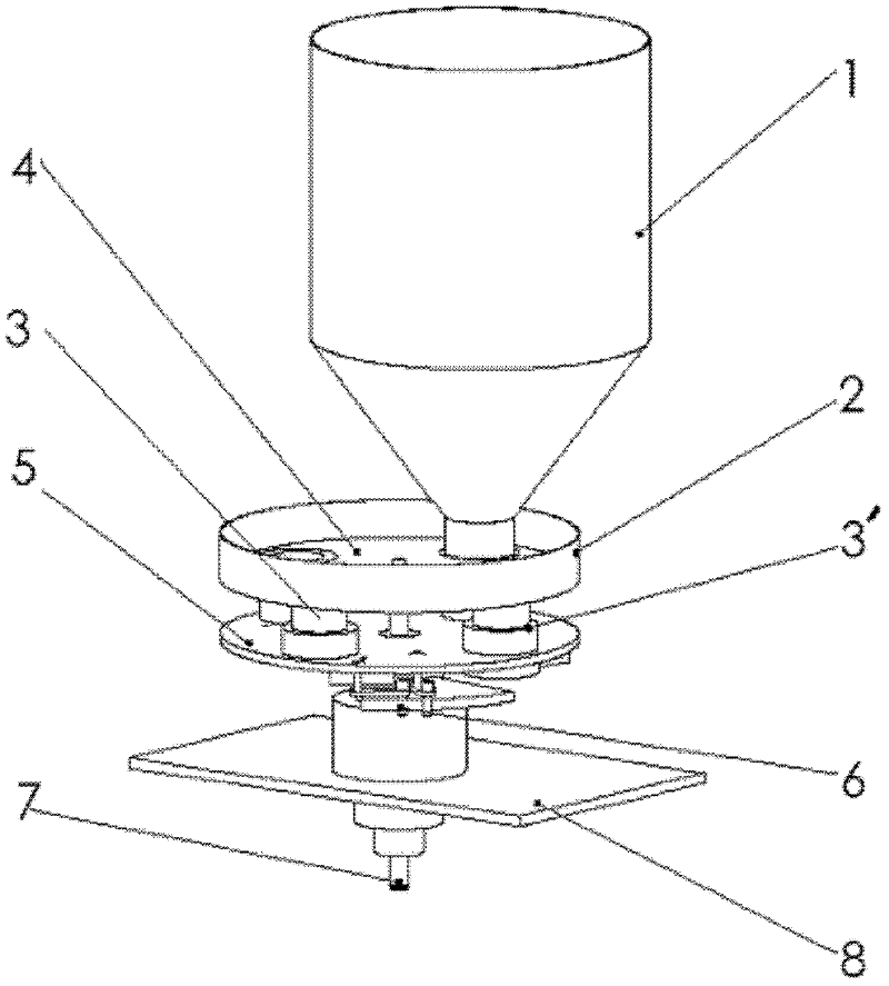
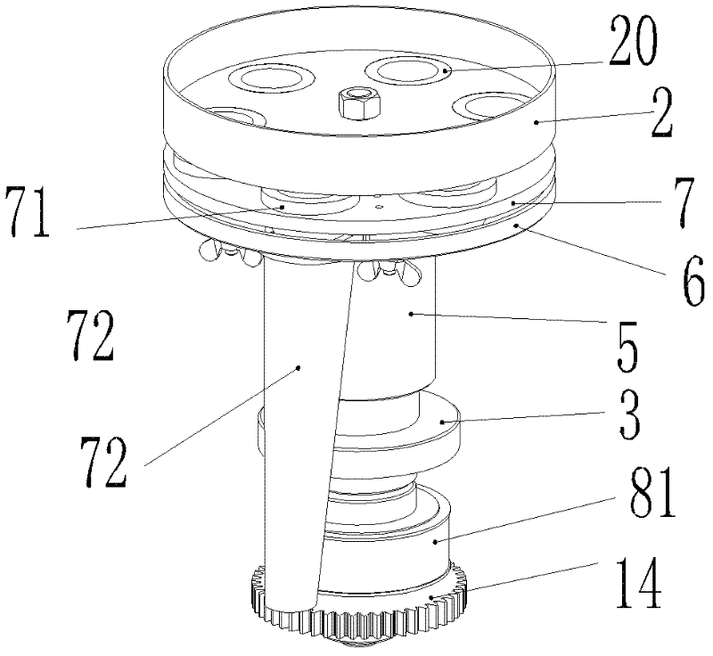
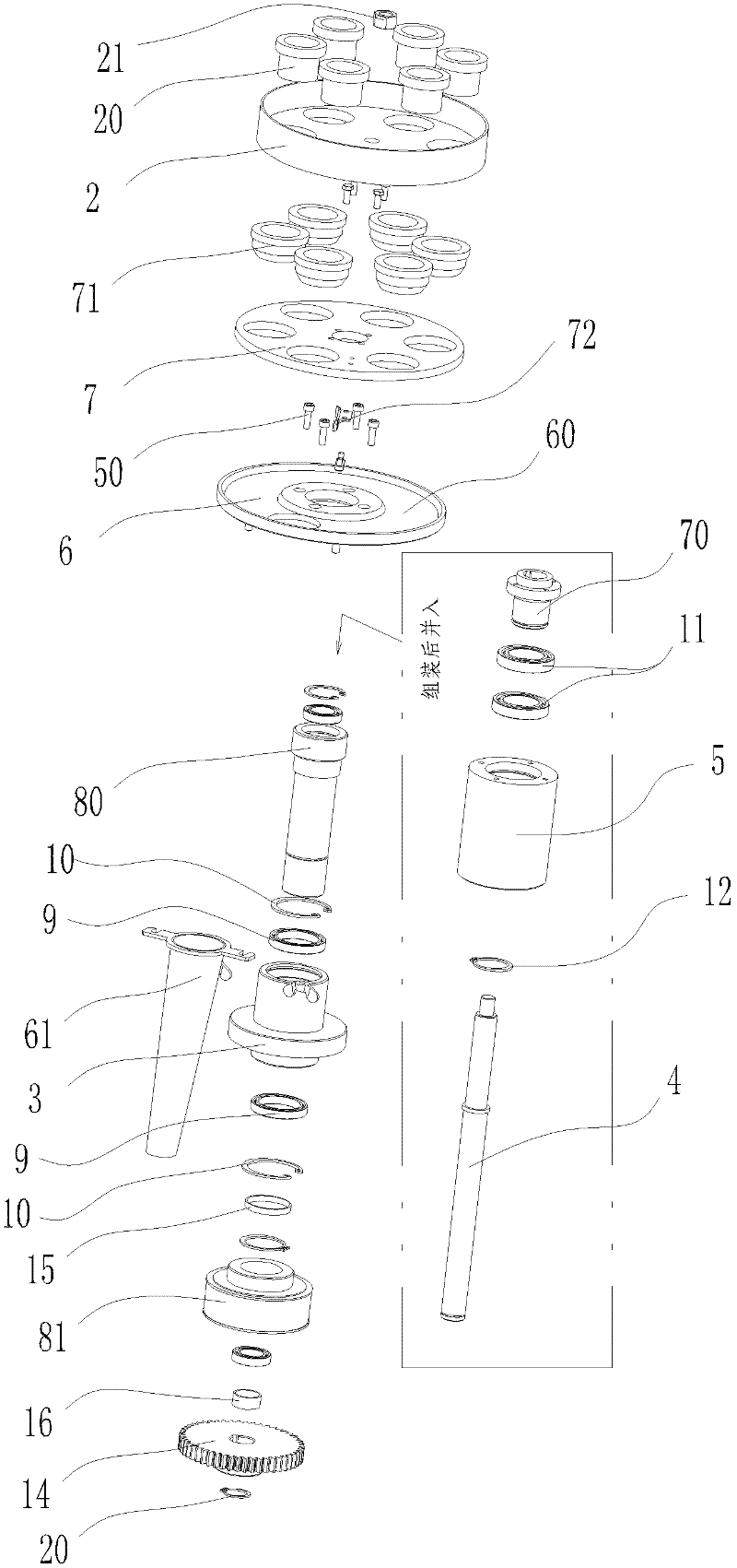
[0022] like Figure 2 to Figure 4 As shown, the non-material door measuring cup type metering mechanism includes a mounting frame 1, a driving motor (not shown in the figure), a material disc 2, an axle seat 3 and a metering disk spindle 4, and the axle seat 3 is fixed on the mounting frame 1, and the metering disk The main shaft 4 is sleeved on the shaft seat 3 and driven by the drive motor to rotate. The material disc 2 used to accept the material is installed on the top of the metering disc main shaft 4 through the nut 21; The upper sleeve 5 of the upper sleeve 5, the top of the upper sleeve 5 is fixed on the blanking plate 6 sleeved on the upper part of the main shaft 4 of the metering disc through the hexagon socket head screw 50; 7. The middle plate 7 is fixed on the upper end of the middle plate base 70 sleeved on the upper part of the metering disc main shaft 4, and the lower end of the middle plate base 70 is fixed in the center cavity of the upper sleeve 5 and the bl...


PUM


Abstract

The invention provides a measuring cup type metering mechanism without a bin gate. The metering mechanism comprises a mounting frame, a driving motor, a material circular disc, a shaft seat and a metering disc main shaft, wherein the shaft seat is fixed on the mounting frame, the metering disc main shaft is sheathed on the shaft seat and driven by the driving motor to rotate, and the material circular disc is mounted at the top end of the metering disc main shaft; an upper sleeve sheathed on the metering disc main shaft is connected on the upper side of the shaft seat, and a blanking disc sheathed at the upper part of the metering disc main shaft is fixedly arranged at the top end of the upper sleeve; a middle disc is arranged between the material circular disc and the blanking disc, the middle disc is fixed on a middle disc base sheathed at the upper part of the metering disc main shaft, and the lower end of the middle disc base is fixed in a central inner cavity of the upper sleeve and the blanking disc and can rotate relatively to the blanking disc; and a plurality of groups of upper and lower measuring cups, which are paired and connected in up-and-down sliding manner, are respectively correspondingly arranged on the material circular disc and the middle disc, a concave ring groove matched with lower ports of the lower measuring cups on the middle disc is arranged on the blanking disc, and a discharge nozzle running through a through hole in the concave ring groove is mounted at the lower end of the blanking disc.

Description

【Technical field】 [0001] The invention relates to a measuring cup type metering mechanism, in particular to a measuring cup type metering mechanism without a material door. 【Background technique】 [0002] Currently used gate-measuring cup metering mechanism such as figure 1 As shown, the mechanism includes a feed hopper 1, an upper turntable 4, a lower turntable 5 and a base 8. During work, the material falls into the upper measuring cup 3 of the upper turntable 4 through the supply hopper 1 by gravity, and enters the upper turntable 5 on the lower turntable 5. In the lower measuring cup 3' that fits on the upper turntable 4, wherein, the lower turntable 5 and the upper turntable 4 are generally provided with 4-6 disc openings, and the upper and lower measuring cups (3, 3') that cooperate with each other are installed correspondingly at the disc openings. ), the corresponding material door 6 is installed at the lower end of each group of upper and lower measuring cups (3, 3...

Claims


Application Information

Patent Timeline
IPC IPC(8): B65B1/36
Inventor 高粤杰
Owner 珠海瑞创科技发展有限公司
Why Eureka
Try Eureka