Hydraulic fatigue test system of connecting rod

A fatigue test, hydraulic technology, applied in the direction of machine gear/transmission mechanism testing, using repetitive force/pulse force to test the strength of materials, etc. The effect of reference value

Inactive Publication Date: 2012-03-28
ZHEJIANG UNIV
View PDF3 Cites 35 Cited by
  • Summary
  • Abstract
  • Description
  • Claims
  • Application Information

AI Technical Summary

Problems solved by technology

Because no matter whether it is a ductile material or a brittle material, there are no obvious

Method used


Image

  • Hydraulic fatigue test system of connecting rod
  • Hydraulic fatigue test system of connecting rod
  • Hydraulic fatigue test system of connecting rod

Examples


Embodiment Construction

[0018] The present invention will be described in detail below in conjunction with the accompanying drawings.

[0019] 1. The overall composition of the engine connecting rod hydraulic fatigue test system

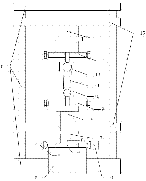
[0020] The test system consists of two components, the test bench and the control system. According to the functions, the test bench includes: pumping station mechanism, hydraulic loading mechanism, test bench body, clamping and bearing mechanism.

[0021] test system such as figure 1 shown.

[0022] 2. Introduction of each part of the test system

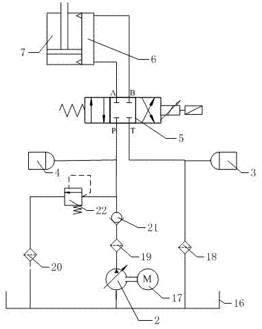
[0023] Pump station mechanism

[0024] like figure 2 As shown, the pumping station mechanism includes a hydraulic pumping station 2, an oil tank 16 and a motor 17. The main function of the pumping station mechanism is to provide hydraulic power for the system and provide hydraulic oil with a certain pressure and a certain flow rate to the hydraulic loading mechanism. The hydraulic pump station 2 of this test system is an ...


PUM


Abstract

The invention discloses a hydraulic fatigue test system of a connecting rod. The system mainly consists of a test bench and a control system, wherein the test bench comprises a pump station mechanism, a hydraulic loading mechanism, a test bench body and a clamping and bearing mechanism; the pump station mechanism, the hydraulic loading mechanism and the clamping and bearing mechanism are all fixed on the test bench body; the hydraulic loading mechanism is connected with the pump station mechanism; and the clamping and bearing mechanism is connected with the hydraulic loading mechanism. In the test system disclosed by the invention, as the tension-compression loading for the connecting rod is asymmetric loading, the system realizes any duty ratio, can simulate multiple working conditions to load and thus can be widely applied to the fatigue test of the connecting rod in a large range.

Description

technical field [0001] The invention relates to a test device for an engine connecting rod, in particular to a test system for testing the fatigue characteristics of an engine connecting rod by means of hydraulic tension and compression loading. Background technique [0002] Since the development of the engine, the mechanical load has been continuously improved, and the reliability and strengthening indicators of the engine have also been improved accordingly. [0003] The connecting rod is undoubtedly a very important moving part in the engine. Its function is to connect the piston and the crankshaft, and transmit the force acting on the piston to the crankshaft, so that the reciprocating motion of the piston is converted into the rotational motion of the crankshaft, and the external output works. The small end of the connecting rod is reciprocating, the large end is rotating, and the shaft is moving in a complex plane. Therefore, the stress of the connecting rod is very co...

Claims


Application Information

Patent Timeline
IPC IPC(8): G01N3/36G01M13/02
Inventor 刘震涛刘宏瑞李建锋刘海军俞小莉
Owner ZHEJIANG UNIV
Why Eureka
Try Eureka