Method for determining use priority of control surfaces of aircraft with multiple control surfces at take-off and landing stages

A multi-control surface, aircraft take-off technology, applied in the field of flight control, can solve the problems of affecting the aircraft, slow aircraft control response, affecting the flight performance of the aircraft, etc., and achieve the effect of reducing adverse costs and improving flight performance.

Inactive Publication Date: 2014-04-02
NORTHWESTERN POLYTECHNICAL UNIV
View PDF4 Cites 0 Cited by
  • Summary
  • Abstract
  • Description
  • Claims
  • Application Information

AI Technical Summary

Problems solved by technology

The aircraft with multiple control surfaces can use various control methods to meet the control requirements, but the cost of different control methods is also different. This is mainly because, firstly, the deflection of the control surfaces can not only generate the control moment, but also affect the lift-drag characteristics of the aircraft. If the control method that affects the lift-drag characteristics of the aircraft is selected, it will affect the flight performance of the aircraft; secondly, the deflection angle and deflection rate of the steering gear on the control surface are limited, so the control surface The generated control torque is limited, and it will take a certain amount of time to reach the desired control torque. If too many control surfaces with low steering gear deflection rate are selected, although the desired control torque can still be achieved in the end, the control response of the aircraft will be affected. Slower, which affects the agility of the aircraft

Method used


Image

  • Method for determining use priority of control surfaces of aircraft with multiple control surfces at take-off and landing stages
  • Method for determining use priority of control surfaces of aircraft with multiple control surfces at take-off and landing stages
  • Method for determining use priority of control surfaces of aircraft with multiple control surfces at take-off and landing stages

Examples


Embodiment 1

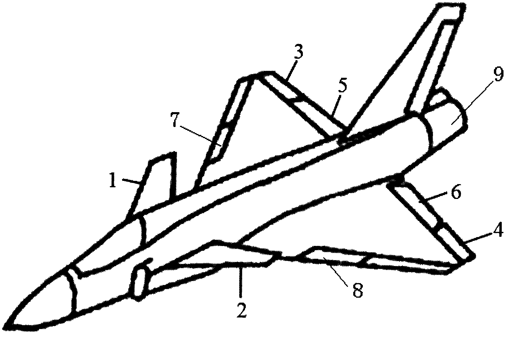
[0018] Refer to attached figure 1 In this embodiment, the method of the present invention is used to determine the use priority of each control surface of a certain type of multi-control surface aircraft during takeoff and landing. In the embodiment, the control surfaces suitable for the multi-control surface aircraft to be used in the take-off and landing stages include: the right close-coupled canard 1, the left close-coupled canard 2, the right outer elevon 3, the left outer elevon 4, The right inner elevon 5, the left inner elevon 6, the right leading edge maneuverable flap 7, the left leading edge maneuverable flap 8 and the rudder, since the rudder is the only heading control surface, it does not need to be controlled The allocation process determines its deflection angle, so the control surfaces that need to be prioritized in this embodiment are the right close-coupled canard 1, the left close-coupled canard 2, the right outer elevon 3, and the left outer elevon Wing 4...

Embodiment 2

[0030] In the present embodiment, the control surface that multi-control surface aircraft is suitable for use in the take-off and landing stage is except comprising the canard in embodiment 1 (deflection angle is denoted as δ c ), elevon (deflection angle is denoted as δ e ), leading edge maneuvering flaps (deflection angle is denoted as δ le ), it also includes the thrust vector (the deflection angle of the thrust vector nozzle is denoted as δ tv )

[0031] In this embodiment, the usable control surface deflection angle range and deflection rate are shown in Table 2:

[0032] Table 2

[0033] control surface

Minimum declination

Maximum declination

Yaw angular velocity

canard

-55°

25°

±50° / s

Elevon

-25°

25°

±50° / s

leading edge motorized flap

-10°

30°

±20° / s

thrust vectoring nozzle

-25°

25°

±25° / s

[0034] In this embodiment, the reference control ...


PUM


Abstract

The invention provides a method for determining the use priority of control surfaces of an aircraft with multiple control surfces at a taking off and landing stage. In the method, the use priority of the control surfaces is determined according to the formula: Jdeltai=aLRL deltai+amRmdeltai+arlRrldeltai, wherein, deltaCmdeltai is pitch control efficacy of the ith control surface, RLdeltai is the deflection speed of the i control surface, and Rldelta0 is the deflection speed of the reference control surface. By adopting the method, the requirements of the aircraft on the lift drag characteristics, the efficacy of the control surfaces and the deflection capability of a steering engine at the taking off and landing stage can be embodied and the use priority of the control surfaces of the aircraft can be determined according to the requirements so that the control surfaces with high priority can be selected in the presence of a plurality of control modes, thus lowering the adverse price during the control process and improving the flight performance at the taking off and landing stage of the aircraft.

Description

technical field [0001] The invention relates to the field of flight control, in particular to a method for determining the use priority of each control surface in the take-off and landing stages of an aircraft with multiple control surfaces. Background technique [0002] The three control surfaces of the traditional layout aircraft, including the elevator, aileron and rudder, respectively correspond to the attitude control in the three directions of pitch, roll and yaw. The number of control surfaces is equal to the number of control expected parameters, and the control method is unique. In order to meet the expected performance requirements, modern new aircraft generally introduce some new control surfaces. For example, in order to obtain maneuverability at high angle of attack, a close-coupled canard is introduced; in order to obtain post-stall maneuverability and maneuverability, thrust vectoring is introduced; in order to improve takeoff and landing performance, a lift d...

Claims


Application Information

Patent Timeline
Patent Type & Authority Patents(China)
IPC IPC(8): G05D1/10
Inventor 刘艳高正红颜世伟豆国辉
Owner NORTHWESTERN POLYTECHNICAL UNIV
Why Eureka
Try Eureka