Isolation switch conductor

A technology of isolating switches and conductors, which is applied to electric switches, air switch parts, contacts, etc., can solve the problems of high requirements for production and debugging personnel, large number of parts, and unfavorable on-site observation and debugging, so as to avoid touching fingers. damage effect

Active Publication Date: 2012-03-28
JIANGSU RUGAO HIGH VOLTAGE ELECTRIC APP
View PDF6 Cites 3 Cited by
  • Summary
  • Abstract
  • Description
  • Claims
  • Application Information

AI Technical Summary

Problems solved by technology

The disadvantages of this structure are: a large number of parts, high matching precision requirements, and high requirements for production and debugging personnel; it is a closed structure, which is not conducive to on-site observation and debugging, and it is not easy to find hidden troubles

Method used


Image

  • Isolation switch conductor
  • Isolation switch conductor
  • Isolation switch conductor

Examples


Embodiment Construction

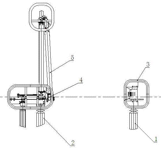
[0014] figure 1 It shows a schematic diagram of the structure of the isolating switch of the present invention, including a pair of insulators 1 and 2. The insulator 1 on one side is provided with a static contact part 3, and the insulator 2 on the other side is connected to the movable contact part through a folded arm type conductive rod 5. 4. The folding-arm conductive rod 5 is driven by the operating mechanism to unfold or fold up so as to push the moving contact part 4 to cooperate with the static contact part 3 to realize opening and closing.

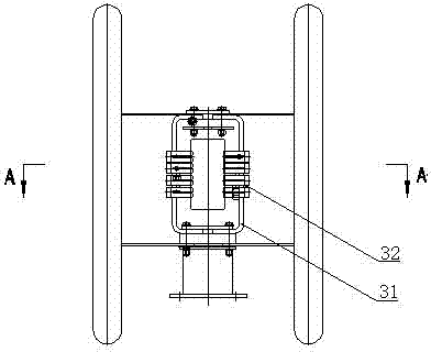
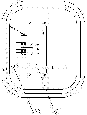
[0015] Figure 2 to Figure 4 The structure of the static contact portion 3 is shown, which includes a static contact seat 31, contact fingers 32, a guide plate 33 and a compression spring 34. The static contact seat 31 is in the shape of a frame, and the inner walls on both sides are connected with ohmic tensioners. The open contact finger 32 is provided with a compression spring 34 between the contact finger 32 and the inner wa...


PUM


Abstract

The invention relates to an isolation switch conductor. The isolation switch conductor comprises a static contact part and a moving contact part which is matched with the static contact part to achieve switch-on and switch-off, wherein the static contact part comprises a frame-shaped static contact seat; the inner walls of two sides of the static contact seat are provided with ohm-shaped contact fingers; a compression spring is arranged between a contact finger and the inner wall of the static contact seat; the upper end and the lower end of the static contact seat are provided with guide plates, and the front end of each guide plate bends outwardly and is opened; the moving contact part comprises a rectangular frame-type contact knife which can be embedded in the contact finger; the upper end and the lower end of the contact knife are respectively provided with guide roller wheels through supports; when in switch-on, the moving contact part moves towards the static contact part; the upper guide roller wheel or the lower guide roller wheel of the contact knife contacts with the corresponding static contact guide plate in priority; and when the guide lower contact of the guide plate is shoved off and is embedded in the ohm-shaped contact fingers, switch-on pressure is provided by the elastic deformation of the compression spring.

Description

technical field [0001] The invention relates to an isolating switch conductor, in particular to an open type isolating switch conductor with simple structure, low matching precision and easy to find hidden troubles. Background technique [0002] The isolating switch is mainly used to reliably isolate the part that needs to be powered off from the live part in the high-voltage power distribution device to ensure the safety of maintenance work. The traditional isolating switch conductors include a pair of moving contacts and static contacts that can be fitted or separated to realize opening and closing. The static contacts are cylindrical, and the moving contacts include a fixed seat. The guide rod is installed outside the fixed seat to fix the quincunx-shaped contact finger. When switching on, the operating mechanism drives the static contact to move toward the moving contact, and the sliding guide rod retracts relative to the fixed seat and the contact finger, so that the s...

Claims


Application Information

Patent Timeline
Patent Type & Authority Applications(China)
IPC IPC(8): H01H31/02H01H1/00H01H3/32
Inventor 马山华谢杨尹韵梅徐荣蔡海锋
Owner JIANGSU RUGAO HIGH VOLTAGE ELECTRIC APP
Why Eureka
Try Eureka