Connecting structure of charging interface

A charging interface and connection structure technology, which is applied in the direction of connecting, joining/disconnecting connected parts, two-part connecting device, etc., can solve the problems of increasing the difficulty of plugging, high manufacturing cost, and no guide mechanism, etc., to achieve The effect of prolonging the service life, eliminating potential safety hazards, and being convenient to use

Inactive Publication Date: 2012-03-28
ZHANGJIAGANG UCHEN NEW ENERGY TECH CO LTD
View PDF9 Cites 2 Cited by
  • Summary
  • Abstract
  • Description
  • Claims
  • Application Information

AI Technical Summary

Problems solved by technology

[0002] The connection structure of some current charging interfaces, that is, the connection structure of the socket and the plug, has not been equipped with an anti-unplugging mechanism to prevent accidental extraction, which has a large safety hazard, especially for the charging interface used for high-voltage AC as a charging source. Danger
The main reason for not installing an anti-tear mechanism is that the existing anti-tear structures are relatively complicated, which makes the structure of the entire charging interface more complicated and the manufacturing cost is higher
In addition, some of the current charging interfaces have poor plug sealing performance and are prone to water ingress; moreover, there is no obvious guide mechanism for indicating the plugging position on the socket and the socket, which increases the difficulty of plugging.

Method used


Image

  • Connecting structure of charging interface
  • Connecting structure of charging interface
  • Connecting structure of charging interface

Examples


Embodiment Construction

[0017] Specific embodiments of the present invention will be described in detail below in conjunction with the accompanying drawings.

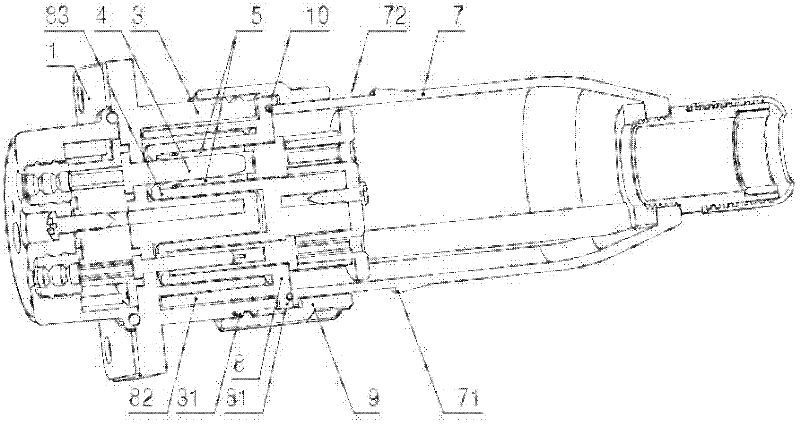
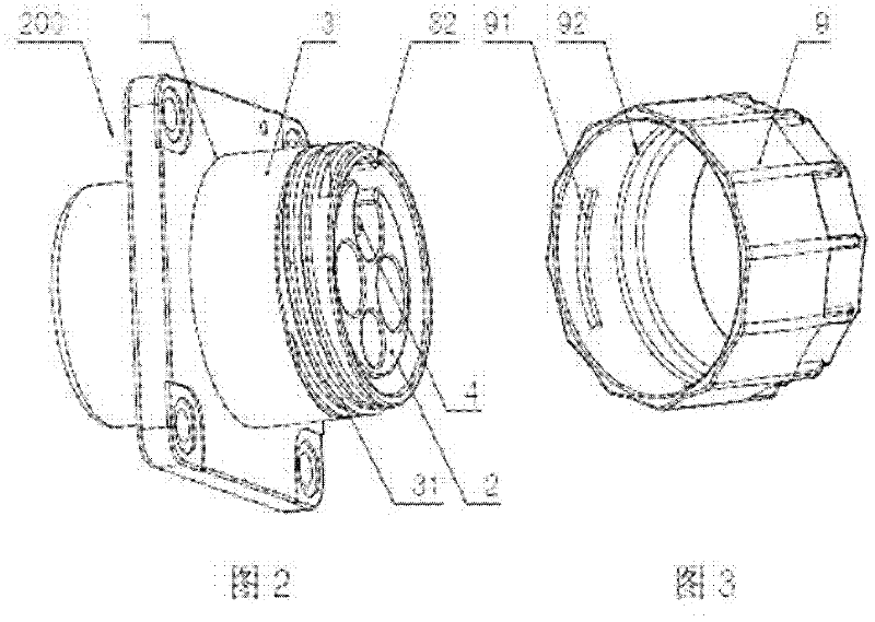
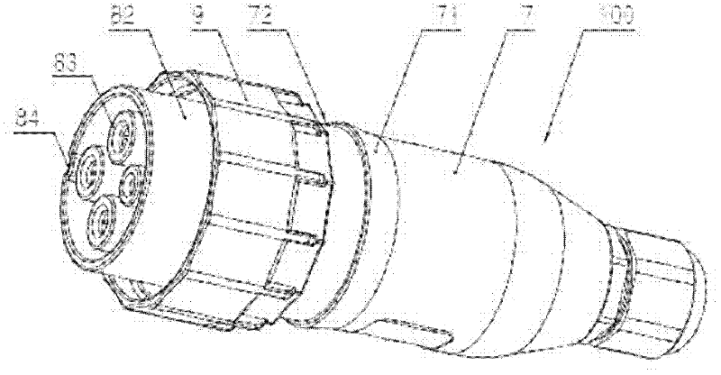
[0018] Such as figure 1 , figure 2 and image 3 As shown, the connection structure of the charging interface of the present invention includes a plug 100 and a socket 200, and the socket 200 includes: a socket housing 1 and a socket body mounting seat 2 arranged in the socket housing 1, and the connection of the socket housing 1 The end is provided with a circular socket barrel 3, and the plug 100 includes: a plug body mounting base 8 and a plug housing 7 connected to the plug body mounting base 8, and a movable sleeve on the plug housing 7 and the plug body mounting base 8 Pull-proof cover 9, such as Figure 4 As shown, the inner wall of the pull-out prevention cover 9 is sequentially provided with a circumferential internal connecting thread 91 and a limiting boss 92 along the pull-out direction, and the plug body mounting seat 8 is prov...


PUM


Abstract

The invention discloses a connecting structure of a charging interface, which is simple in structure and can reduce the manufacturing cost. The connecting structure comprises a plug and a socket, wherein the socket comprises a socket shell and a socket body installing seat which is arranged in the socket shell, and a connecting end of the socket shell is provided with a circular socket barrel; the plug comprises a plug body installing seat and a plug shell which is connecting with the plug body installing seat, a pulling preventing cover is movably sheathed on the plug shell and the plug body installing seat, the inner wall of the pulling preventing cover is provided with circumferential inner connecting threads and a limiting boss in sequence along the pulling-out direction, a circumferential in-place boss is arranged on the plug body installing seat, and the limiting boss and the inner connecting threads are positioned at two sides of the placing-in boss; and outer connecting threads which are matched with the inner threads are arranged on the outer wall of the circular socket barrel. By the mutual matching of the pulling preventing cover and the circular socket barrel of the socket shell, the connecting structure can achieve the purpose that the pulling by mistake is prevented, and eliminates potential safety hazards.

Description

technical field [0001] The invention relates to a charging interface, in particular to a connection structure of the charging interface. Background technique [0002] The connection structure of some current charging interfaces, that is, the connection structure of the socket and the plug, has not been equipped with an anti-unplugging mechanism to prevent accidental extraction, which has a large safety hazard, especially for the charging interface used for high-voltage AC as a charging source. Danger. The main reason for not adding an anti-tear mechanism is that the existing anti-tear structures are relatively complicated, which makes the structure of the entire charging interface more complicated and the manufacturing cost is higher. In addition, the plugs of some current charging interfaces have poor sealing performance and are prone to water ingress; moreover, there is no obvious guide mechanism for indicating the insertion position on the socket and the socket, which in...

Claims


Application Information

Patent Timeline
Patent Type & Authority Applications(China)
IPC IPC(8): H01R13/622H01R13/642H01R13/631H01R13/52H01R24/00
Inventor 王建东郑晓波陈建刚
Owner ZHANGJIAGANG UCHEN NEW ENERGY TECH CO LTD
Why Eureka
Try Eureka