
Link time delay detection method, source terminal, destination terminal and system

A detection method and technology of a detection system, applied in the field of communication, can solve problems such as failure to send business messages normally, failure of detected links to work normally, and high labor costs

Inactive Publication Date: 2012-03-28
HUAWEI TECH CO LTD
View PDF4 Cites 22 Cited by
  • Summary
  • Abstract
  • Description
  • Claims
  • Application Information

AI Technical Summary

Problems solved by technology

[0004] In the process of realizing the above-mentioned link delay detection, the inventor found at least the following problems in the prior art: by manually configuring the transmission loopback of the link to be detected, all the data in the link are blocked in the loop to be detected Back in the middle, resulting in the failure to send business packets normally, causing the detected link to fail to work normally
And each time a different link is detected, manual configuration and loopback removal must be performed again, and the labor cost is high

Method used


Image

  • Link time delay detection method, source terminal, destination terminal and system
  • Link time delay detection method, source terminal, destination terminal and system
  • Link time delay detection method, source terminal, destination terminal and system

Examples


Embodiment 1

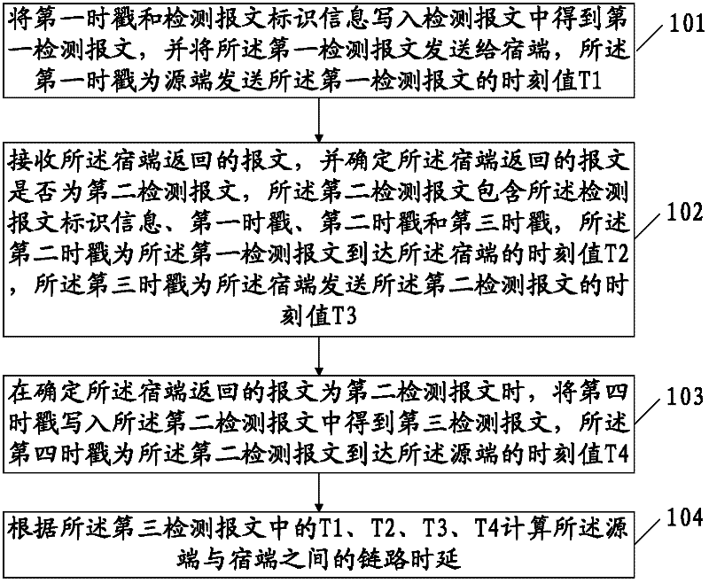
[0070] The embodiment of the present invention provides a link delay detection method, such as figure 1 As shown, the method includes:

[0071] 101. Write the first time stamp and the detection message identification information into the detection message to obtain the first detection message, and send the first detection message to the sink end, and the first time stamp is sent by the source end The time value T1 of the first detection message.

[0072] 102. Receive the packet returned by the sink, and determine whether the packet returned by the sink is a second detection packet, where the second detection packet includes the detection packet identification information and a first timestamp , a second time stamp and a third time stamp, the second time stamp is the time value T2 when the first detection message arrives at the sink, and the third time stamp is the time when the sink sends the second The time value T3 of detecting the packet.

[0073] 103. When it is determi...

Embodiment 2

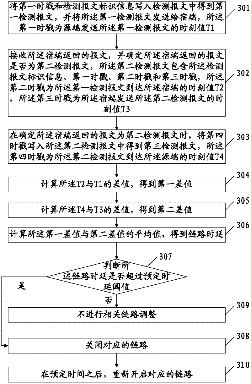
[0082] An embodiment of the present invention provides a link delay detection method, such as image 3 shown, including:

[0083] 301. Write the first time stamp and detection message identification information into the detection message to obtain the first detection message, and send the first detection message to the sink, and the first time stamp is sent by the source The time value T1 of the first detection message.

[0084] Wherein, the first timestamp is the time value T1 at which the source sends the first detection message, which is written into the message field of the detection message, for example, as shown in Table 1, it is a complete PPP message, Write T1 to the first 4 bytes of the message field. The address and control fields in the PPP message occupy 1 byte respectively, the protocol field occupies 2 bytes, the first 16 bytes of the message field are used to store 4 timestamp information, and the remaining 33 bytes in the message field It may not be used in ...

Embodiment 3

[0123] An embodiment of the present invention provides a source, such as Figure 5 As shown, it includes: a first time stamp unit 51 , a source determination unit 52 , a fourth time stamp unit 53 , and a calculation unit 54 .

[0124] The first time stamp unit 51 is configured to write the first time stamp and the detection message identification information into the detection message to obtain the first detection message, and send the first detection message to the sink end, the first detection message A timestamp is the time T1 when the source sends the first detection message.

[0125] The source determining unit 52 is configured to receive the message returned by the sink, and determine whether the message returned by the sink is a second detection message, and the second detection message includes the detection message identifier information, a first timestamp, a second timestamp, and a third timestamp; the second timestamp is the time value T2 when the first detection m...


PUM


Abstract

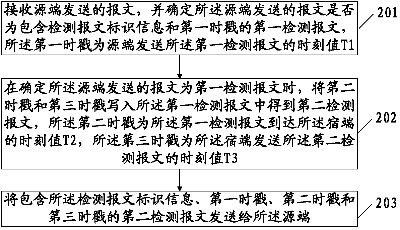
The embodiment of the invention provides link time delay detection method, source terminal, destination terminal and system, which can prevent time delay detection from influencing the current network service, and relates to the field of communication technology. The method comprises the following steps: a first time stamp and detection message identification information are written into a first detection message and sent to a destination terminal, and the first time stamp is the time T1 at which the source terminal sends the first detection message; a message returned by the destination terminal is received, whether the received message is a second detection message is confirmed, the second detection message comprises detection message identification information, the first time stamp, a second time stamp and a third time stamp, the second time stamp is the time T2 at which the first detection message reaches the destination terminal, and the third time stamp is the time T3 at which the destination terminal sends the second detection message; a fourth time stamp, the time T4 at which the second detection message reaches the source terminal, is written into the second detection message; and the link time delay between the source terminal and the destination terminal is calculated according to the T1, T2, T3 and T4.

Description

technical field [0001] The invention relates to the field of communication technology, in particular to a link time delay detection method, a source end, a sink end and a system. Background technique [0002] In order to ensure communication quality, in point-to-point protocol (Point to Point Protocol, PPP) application scenarios, it is usually necessary to detect the data transmission delay of the transmission link, so as to grasp the working status of the transmission link. Especially in a multilink point-to-point protocol (Multilink Point to Point Protocol, MLPPP) application scenario, by performing link delay detection on each transmission link, it can provide a basis for analysis and control of multiple links. [0003] The traditional link delay detection adopts the interface remote loopback technology. Specifically, in the PPP application scenario, the data transmission loopback is manually configured for the link to be detected, so as to detect the transmission delay o...

Claims


Application Information

Patent Timeline
Patent Type & Authority Applications(China)
IPC IPC(8): H04L12/26H04L12/56
Inventor 韩炜
Owner HUAWEI TECH CO LTD
Learn More