

Displacement sensor
A displacement sensor and diaphragm technology, applied in the field of displacement sensors, can solve the problems of increasing defective products, strain gauge deviation, etc., and achieve the effect of improving sensitivity
- Summary
- Abstract
- Description
- Claims
- Application Information
AI Technical Summary
Problems solved by technology
Method used
Image

Examples
Embodiment Construction
[0050] Hereinafter, the function, configuration, and operation of a displacement sensor according to a preferred embodiment of the present invention will be described in detail with reference to the accompanying drawings.
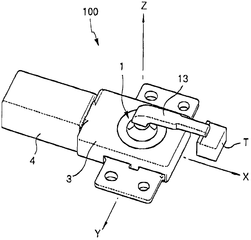
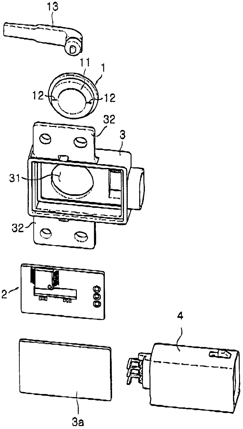
[0051] figure 1 is a perspective view illustrating a displacement sensor according to an embodiment of the present invention, and figure 2 is in figure 1 An exploded bottom perspective view of the displacement sensor illustrated in .
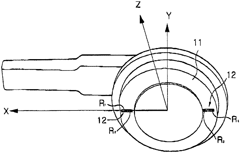
[0052] The displacement sensor 100 according to the embodiment of the present invention includes a sensing body 1 and a signal processing unit 2 . This sensing body 1 is provided on its lower surface with a diaphragm 11 to which strain gauges 12 are attached and an input rod 13 fixed orthogonally to the center of its upper surface, to which the displacement of the mechanical device is transmitted 13. The strain gauge 12 functions to measure the strain of the diaphragm 11 caused by the moment of the input rod 13 , and t...
PUM
 Abstract
Description
Claims
Application Information