Multi-piece valve disk

A multi-piece, valve disc technology, used in multi-way valves, lift valves, valve devices, etc., to achieve the effects of simple assembly, easy disassembly, and high functional reliability

Active Publication Date: 2012-04-04
KRONES AG
View PDF9 Cites 4 Cited by
  • Summary
  • Abstract
  • Description
  • Claims
  • Application Information

AI Technical Summary

Problems solved by technology

However, since the parts of the valve disc are directly supported at the gasket

Method used


Image

  • Multi-piece valve disk
  • Multi-piece valve disk
  • Multi-piece valve disk

Examples


Embodiment Construction

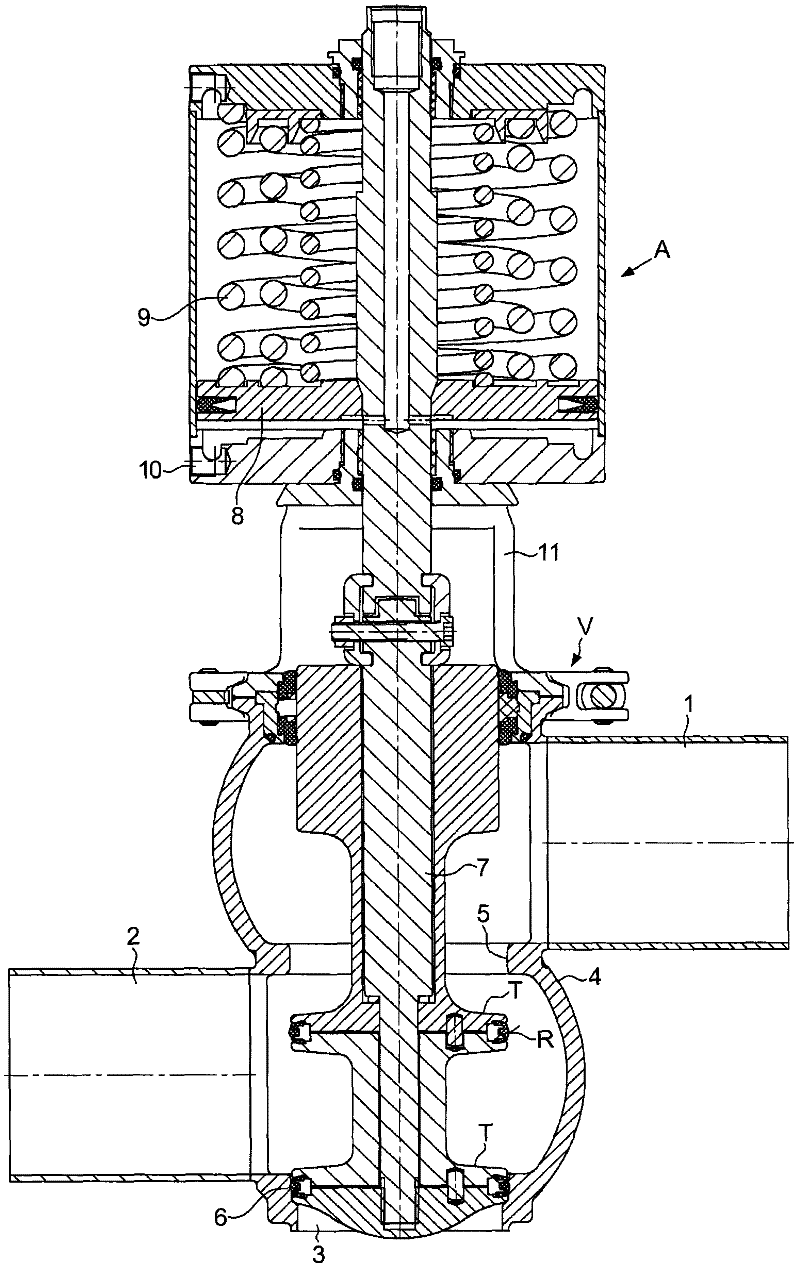
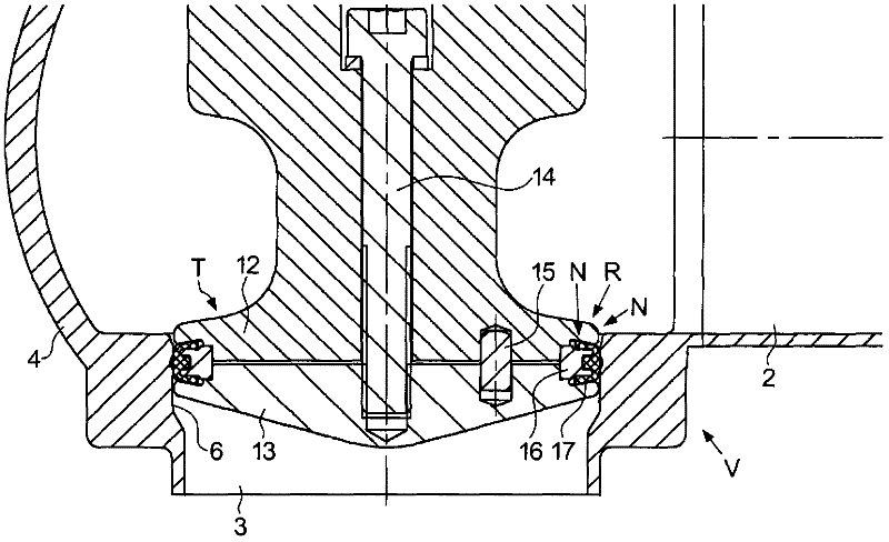
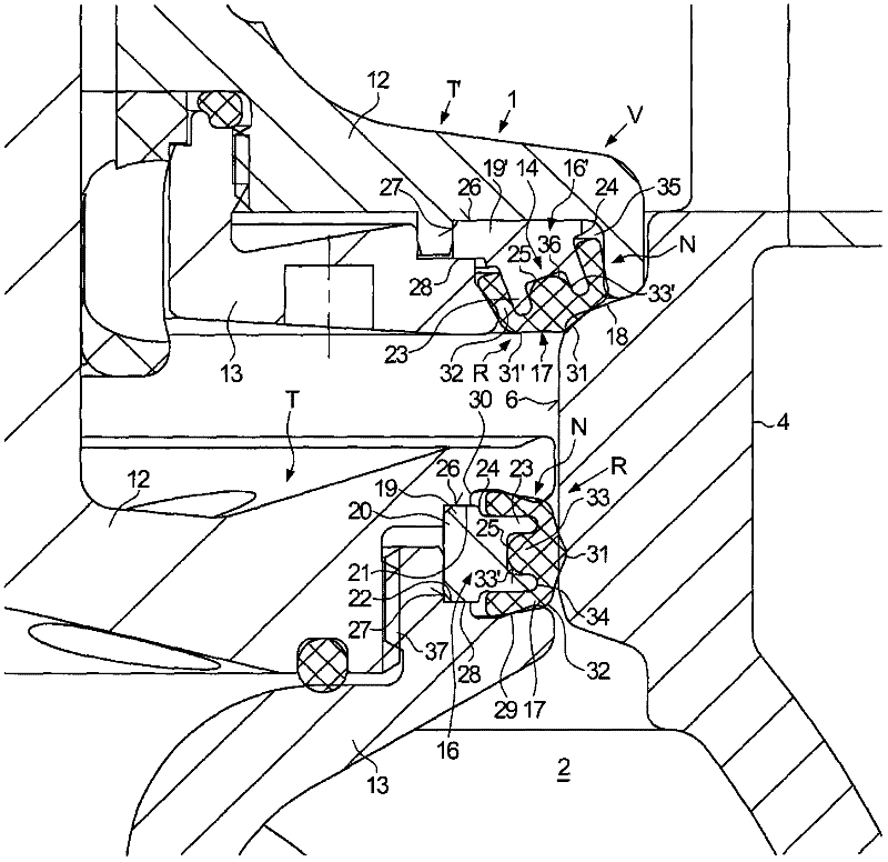
[0026] The invention relates to a multi-part valve disk T having at least one sealing ring arrangement R and also to this sealing ring arrangement R itself. Valve discs T with at least one sealing ring arrangement R are used, for example, in valves with only one or two valve discs in sliding and / or seat valves (single sliding or seat valves); or in valves with two and one seat In the double-seat valve of the disc T that works together. Double seat valves can work which exhibit a combination of seat and slide valve functions, or a combination of both seat valve functions or two slide valve functions. Such double-seat valves are used, for example, for the flow control of beverage products, food, pharmaceuticals or biotechnological products, they must be selectively cleanable in a specific way, must reliably isolate the individual flow paths from each other in the closed position and have a Leakage between flow media is selectively avoided, and they must prevent media exchange b...


PUM

PropertyMeasurementUnit
Shore hardnessaaaaaaaaaa

Abstract

The invention discloses a multi-piece valve disk (T, T'), in particular a multi-piece valve disk (T, T') of a sliding and/or seat valve (V). In the multi-piece valve disk (T, T'), a ring seal (R, R') with an elastic sealing ring (17) with an external sealing zone (31) is placed in a ring groove (N) of the valve disk (T, T') onto a dimensionally stable backup ring (16, 16'), and where an elastic restoring region (33) effectively positioned between the backup ring (16, 16') and the external sealing zone (31) is arranged in the backup ring (16, 16'), the restoring region (33) being embodied in one piece with the sealing ring (17) of its material adjacent to the external sealing zone (31) of the sealing ring (17).

Description

technical field [0001] The invention relates to a multi-piece valve disk according to the preamble of patent claim 1 and a multi-piece valve disk according to the preamble of patent claim 16 Valve disc sealing ring device. Background technique [0002] In the multi-piece valve disc of a double seat valve known from DE 101 47 455 C, which comprises two valve discs, each of which cooperates with the inner wall of the seat to function as a sliding valve, the sealing ring arrangement consists of Composed of three prefabricated parts mounted on each other, consisting of a sealing ring of elastic material, a dimensionally stable gasket and a restoring region for the sealing ring, which is inserted between the sealing ring and the gasket. For example, it is in the shape of an O-ring. Since the gasket is supported radially only at a part of the valve disc, the clamping width of the ring groove for receiving the sealing ring arrangement can only be defined by the metal contact betw...

Claims


Application Information

Patent Timeline
IPC IPC(8): F16K1/44F16K1/46
CPCF16J15/062F16J15/061F16K1/443F16K1/446F16K11/044F16K11/07Y10T137/88038Y10T137/87981F16K1/46
Inventor 梅尔廷·绍尔迪特尔·魏默
Owner KRONES AG
Why Eureka
Try Eureka