Check patentability & draft patents in minutes with Patsnap Eureka AI!

Optical ranging system

An optical distance measurement and light spot technology, applied in the field of distance measurement system, can solve the problems of large measurement error, inconvenient use, and inability to correctly calculate the distance from the optical distance measurement device to the object to be measured, etc.

Active Publication Date: 2012-04-04
PIXART IMAGING INC
View PDF4 Cites 7 Cited by
  • Summary
  • Abstract
  • Description
  • Claims
  • Application Information

AI Technical Summary

Problems solved by technology

[0003] However, when the surface of the object under test is not fully illuminated by the detection light, the optical distance measuring device cannot generate a complete image of the light spot according to the reflected light reflected by the object under test
Therefore, when the optical distance measuring device calculates the distance of the object to be measured, a large measurement error occurs due to the inability to obtain the accurate spot position, so the distance from the optical distance measuring device to the object to be measured cannot be correctly calculated, causing inconvenience in use

Method used


Image

  • Optical ranging system
  • Optical ranging system
  • Optical ranging system

Examples


Embodiment Construction

[0028] In order to make the above and other objects, features, and advantages of the present invention more obvious, the following will be described in detail with the accompanying drawings. In addition, in the drawings of the present invention, only part of the components are shown and components not directly related to the description of the present invention are omitted.

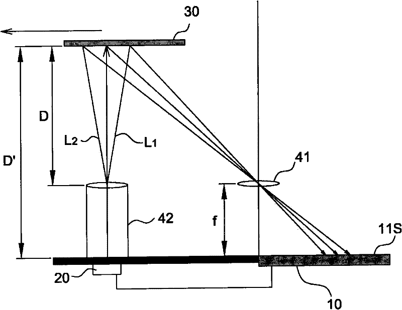
[0029] The invention relates to an optical distance measuring system for distance measurement using optical imaging. Please refer to figure 1 As shown, it shows a schematic diagram of an optical distance measuring system according to an embodiment of the present invention, which includes a sensing device 10 and a light source 20. The light source 20 projects light onto the surface of an object 30, such as light L 1 And L 2 . Light L 1 And L 2 The surface of the object 30 is reflected to the sensing device 10 and forms a light spot. The sensing device 10 can calculate the distance between the object 30 and ...


PUM


Abstract

The invention discloses an optical ranging system which comprises a light source and a sensing device, wherein the light source is used for providing light rays to the surface of an object; the sensing device is used for receiving reflected light rays on the surface of the object and outputs the distance of the object according to the reflected light rays; the sensing device comprises a sensing module and a computing module; the sensing module is used for the reflected light rays and generating an image; and the computing module is used for computing and outputting the distance according to the imaging position and the imaging size of the reflected light rays on the image.

Description

Technical field [0001] The invention relates to a distance measuring system, in particular to an optical distance measuring system capable of compensating the detection distance according to the size and symmetry of the detected light spot. Background technique [0002] In the background art, an optical distance measuring device emits detection light to an object to be measured, and receives the reflected light generated by the detection light reflected by the object to be measured to form a light spot relative to the object to be measured. Then, the optical distance measuring device can use trigonometric functions to calculate the distance between the optical distance measuring device and the object to be measured according to the spatial relationship between the components included in it and the image position of the light spot. [0003] However, when the surface of the test object is not completely illuminated by the detection light, the optical distance measuring device cannot ...

Claims


Application Information

Patent Timeline
Patent Type & Authority Applications(China)
IPC IPC(8): G01C3/32
Inventor 古人豪许恩峰廖祈杰李宜方吕志宏吴宗佑
Owner PIXART IMAGING INC
Features
  • R&D
  • Intellectual Property
  • Life Sciences
  • Materials
  • Tech Scout
  • Unparalleled Data Quality
  • Higher Quality Content
  • 60% Fewer Hallucinations
Learn More