Lens barrel and image pickup device

A technology of lens barrel and camera device, which is applied in the direction of printing device, projection device, installation, etc., can solve the problem of increasing the thickness of the lens barrel, and achieve the effect of good aberration correction

Inactive Publication Date: 2012-04-04
OLYMPUS CORP
View PDF4 Cites 11 Cited by
  • Summary
  • Abstract
  • Description
  • Claims
  • Application Information

AI Technical Summary

Problems solved by technology

[0010] However, if the third group of lenses is composed of five lenses in the above-mentioned manner, it is possible that the lens barrel in the sunken state may be damaged due to the increase in the number of lenses accommodated in the lens barrel including the third group of lenses. increased thickness

Method used


Image

  • Lens barrel and image pickup device
  • Lens barrel and image pickup device
  • Lens barrel and image pickup device

Examples


Embodiment Construction

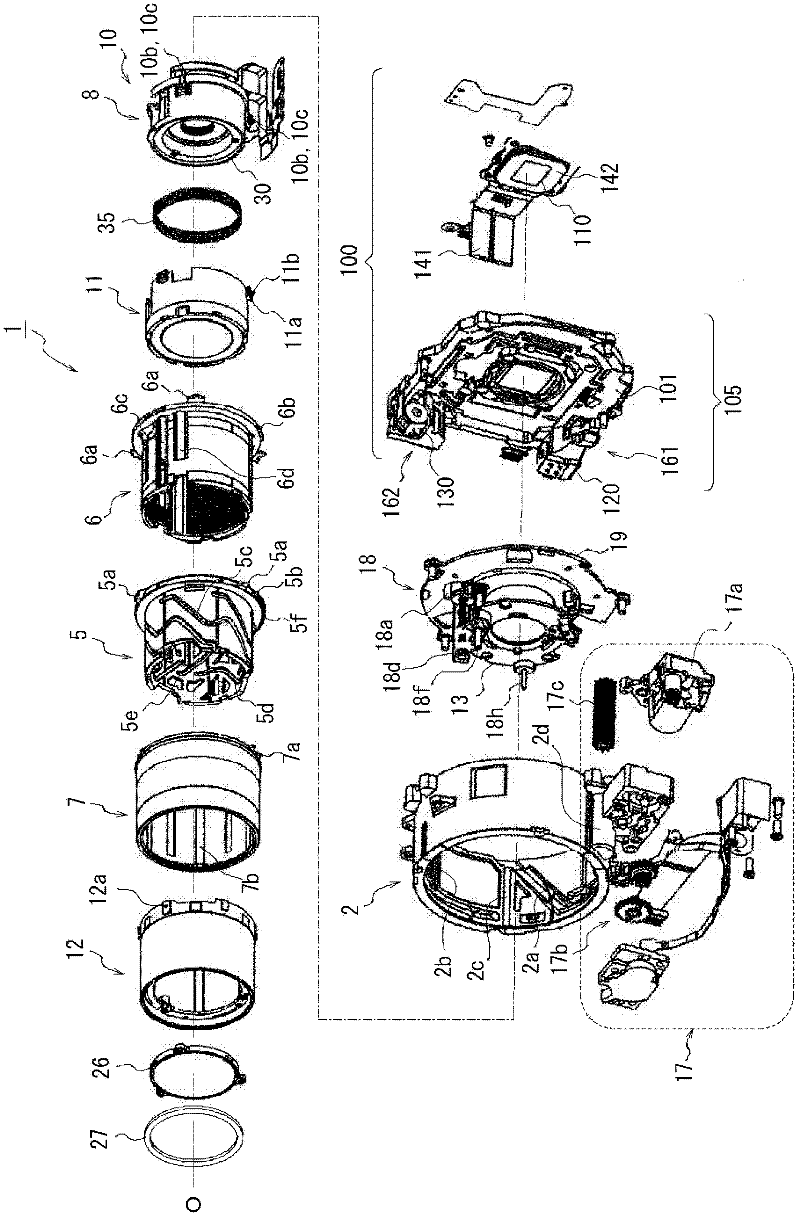
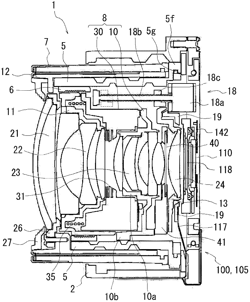
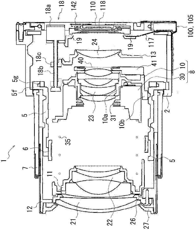
[0102] Hereinafter, an imaging device according to an embodiment of the present invention will be described with reference to the drawings.

[0103] In addition, in the description of the present embodiment, the optical axis (photographic optical axis) of the photographic optical system of the lens barrel is denoted by symbol O. In the direction along the optical axis O (imaging optical axis direction), the subject side (object side) is referred to as the front, and the direction in which each frame member of the lens barrel faces forward is referred to as the extending direction. On the other hand, in the direction along the optical axis O, the imaging side (image side) is referred to as the rear, and the direction in which each frame member faces the rear is referred to as a pull-in direction. In addition, the rotation direction of each component part of a lens barrel is shown by the rotation direction seen from the front side.

[0104] The imaging device of this embodiment...


PUM


Abstract

Provided are a lens barrel and an image pickup device, wherein the lens barrel (1) comprises: a fixed frame (2); a cam frame (5) supported by the fixed frame (2) so as to be rotationally movable in a photographing optical axis direction between a forward movement end and a backward movement end which are each defined in the photographing optical axis direction; a shutter frame (30) which holds a shutter and moves in the photographing optical axis direction in a rotation restricted state, through the rotation of the cam frame (5); a third group frame (10) which holds the third group lens (23) and fixed as fitting, at least in part thereof on the object side, in the inner peripheral side of the shutter frame (30); and a a second group frame (11) which holds the second group lens (22), moves in the photographing optical axis direction in a rotation restricted state, through the rotation of the cam frame (5), and, upon the cam frame (5) being positioned at the backward movement end, fits in, at least in part thereof on the image side, an inner peripheral side of the shutter frame (30).

Description

technical field [0001] The invention relates to a lens barrel and an imaging device. Background technique [0002] In recent years, digital cameras that use imaging elements such as CCD (Charge-coupled Device) and CMOS (Complementary Metal Oxide Semiconductor: Complementary Metal Oxide) sensors to capture images of subjects have been widely used. There are a wide range of digital cameras ranging from high-performance types for professional use to compact and popular types. In particular, in popular digital cameras, miniaturization that can be easily carried anytime and anywhere is pursued. [0003] In addition, most of popular digital cameras use a lens barrel configured to be able to expand and contract over the entire length between an image-capable state and a folded state as a lens barrel equipped with a zoom lens system, and the image-capable state becomes The form is elongated in the optical axis direction and protrudes toward the front of the digital camera casing, ...

Claims


Application Information

Patent Timeline
Patent Type & Authority Applications(China)
IPC IPC(8): G02B7/10G02B15/173G03B17/12
CPCG03B5/00G02B7/08G03B2205/0092G03B2205/00
Inventor 安富晓吉井学山宫国雄藤井尚树宫田正人
Owner OLYMPUS CORP
Why Eureka
Try Eureka