Endoscopic image-capturing objective lens optical system

An optical system and objective lens technology, applied in the field of objective optical systems, can solve the problems of small field of view, unsatisfactory close-up effect, etc., and achieve the effects of improving the field of view, optimizing the curvature of the image plane, and suppressing off-axis aberrations

Active Publication Date: 2017-06-13
东莞市宇光光电科技有限公司
View PDF4 Cites 4 Cited by
  • Summary
  • Abstract
  • Description
  • Claims
  • Application Information

AI Technical Summary

Problems solved by technology

[0004] Chinese patent document CN204101801U describes an endoscope objective lens system composed of a first lens with negative refractive power, a diaphragm, a second lens with positive refractive power, and a third lens from the object side. The structure of the first lens and the third lens that mainly correct aberrations and the second lens with strong optical focus for imaging is sandwiched, and it becomes a three-element lens structure that can achieve miniaturization and can achieve good imaging performance , but its shooting field of view is only about 100 degrees, the field of view is small, and the close-up effect is not ideal

Method used


Image

  • Endoscopic image-capturing objective lens optical system
  • Endoscopic image-capturing objective lens optical system
  • Endoscopic image-capturing objective lens optical system

Examples


Embodiment 1

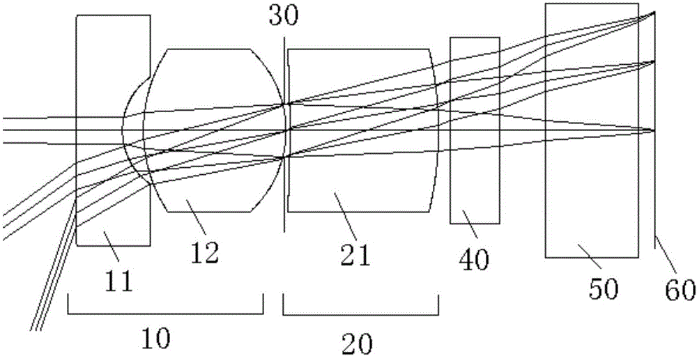
[0077] Please refer to figure 1 , a camera objective optical system for endoscopy includes a first lens group 10 with positive refractive power, a diaphragm 30, a second lens group 20 with positive refractive power, an optical filter 40, and a flat plate from the object side to the image side Glass 50 and photosensitive surface 60 of the chip. The optical filter 40 is mainly used to cut off a specific wavelength, and the flat glass 50 is mainly used to protect the photosensitive surface 60 of the chip.

[0078] The first lens group 10 is composed of a first lens 11 with negative power and a second lens 12 with positive power. The object side and image side of the first lens 11 are spherical, and the object side is Convex, its image side is concave, the object side and image side of the second lens 12 are both convex and spherical, the second lens group 20 is composed of a third lens 21 with positive refractive power, the third Both the object side and the image side of the l...

Embodiment 2

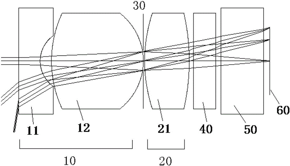
[0083] Please refer to image 3 , a camera objective optical system for endoscopy includes a first lens group 10 with positive refractive power, a diaphragm 30, a second lens group 20 with positive refractive power, an optical filter 40, and a flat plate from the object side to the image side Glass 50 and photosensitive surface 60 of the chip. The optical filter 40 is mainly used to cut off a specific wavelength, and the flat glass 50 is mainly used to protect the photosensitive surface 60 of the chip.

[0084] The first lens group 10 is composed of a first lens 11 with negative refractive power and a second lens 12 with positive refractive power. The object side of the first lens 11 is a plane, and its image side is spherical and concave. , the object side and the image side of the second lens 12 are both convex and spherical, the diaphragm 30 is attached to the image side of the second lens 12, and the second lens group 20 has a positive refractive power The third lens 21 ...

Embodiment 3

[0090] Please refer to Figure 5 , a camera objective optical system for endoscopy includes a first lens group 10 with positive refractive power, a diaphragm 30, a second lens group 20 with positive refractive power, an optical filter 40, and a flat plate from the object side to the image side Glass 50 and photosensitive surface 60 of the chip. The optical filter 40 is mainly used to cut off a specific wavelength, and the flat glass 50 is mainly used to protect the photosensitive surface 60 of the chip.

[0091] The first lens group 10 is composed of a first lens 11 with negative refractive power and a second lens 12 with positive refractive power. The object side and image side of the first lens 11 are both spherical and concave. , the object side and the image side of the second lens 12 are both convex and spherical, the diaphragm 30 is attached to the image side of the second lens 12, and the second lens group 20 has a positive refractive power The third lens 21 is formed...


PUM


Abstract

The invention discloses an endoscopic image-capturing objective lens optical system comprising a first lens group, a diaphragm and a second lens group from an object side to an image side. The first lens group has positive power and comprises a first lens and a second lens. The first lens is made of a plastic material and has at least one spherical surface. The second lens group comprises a third lens having positive power. The endoscopic image-capturing objective lens optical system satisfies a following conditional expression: f / H(L1r1) < 1.5; H (L1r1) / IMH < 1.5; N1 > 1.7; wherein f is the focal length of the endoscopic image-capturing objective lens optical system, H(L1r1) refers to the height of a main light ray corresponding to the maximum image height during conventional observation passing through a surface of the object side of the first lens group, IMH refers to the maximum image height on a corresponding chip light-sensitive surface during conventional observation, and N1 is the refractive index of the first lens. The endoscopic image-capturing objective lens optical system has a small diameter, a wide field of view, and is capable of improving a close-up shot effect.

Description

technical field [0001] The invention relates to an objective optical system, in particular to an endoscope imaging objective optical system. Background technique [0002] Endoscope is a kind of medical optical instrument, which is sent into the body from the outside through the natural cavity of the human body to check the diseases in the body. Scanning the film greatly improves the accuracy of cancer diagnosis, and can carry out some minimally invasive surgical treatment. [0003] In order to alleviate the pain of patients to a greater extent, shorten the recovery time after surgery, reduce the work of doctors, and improve the diagnostic level of visualization and scientific data judgment, it is necessary to further reduce the endoscopic camera system and improve its imaging shooting effect Therefore, it is a technical subject to study and use a larger field of view, smaller and clearer objective lens optical system for endoscopic imaging. [0004] Chinese patent document...

Claims


Application Information

Patent Timeline
Patent Type & Authority Applications(China)
IPC IPC(8): G02B13/00G02B13/06A61B1/00
CPCA61B1/00163G02B13/0035G02B13/06
Inventor 蒋千年涂小芹陈霞光涂孝洲熊强沈小云
Owner 东莞市宇光光电科技有限公司
Why Eureka
Try Eureka