AI technical title is built by PatSnap AI team. It summarizes the technical point description of the patent document.
A technology of optical system and light beam, which is applied in the field of optical system to achieve the effect of good resolution, good aberration correction and simple structure
Inactive Publication Date: 2009-07-15
OLYMPUS CORP
View PDF2 Cites 3 Cited by
Summary
Abstract
Description
Claims
Application Information
AI Technical Summary
This helps you quickly interpret patents by identifying the three key elements:
Problems solved by technology
Method used
Benefits of technology
Problems solved by technology
But it does not use the transparent cover to widen the field of view
Method used
Image
Click on the blue label to locate the original text in one second.
Reading with bidirectional positioning of images and text.
Examples
Embodiment 1
[0043] Example 1 Example 2 Example 3 Example 4
[0044] R1 5.50 5.50 20.00 2.60
[0045] R2 2.60 2.60 2.50 2.60
[0046]d 1.00 1.00 1.50 1.00
[0047] R1 / (R2+d) 1.53 1.53 5.00 1.53
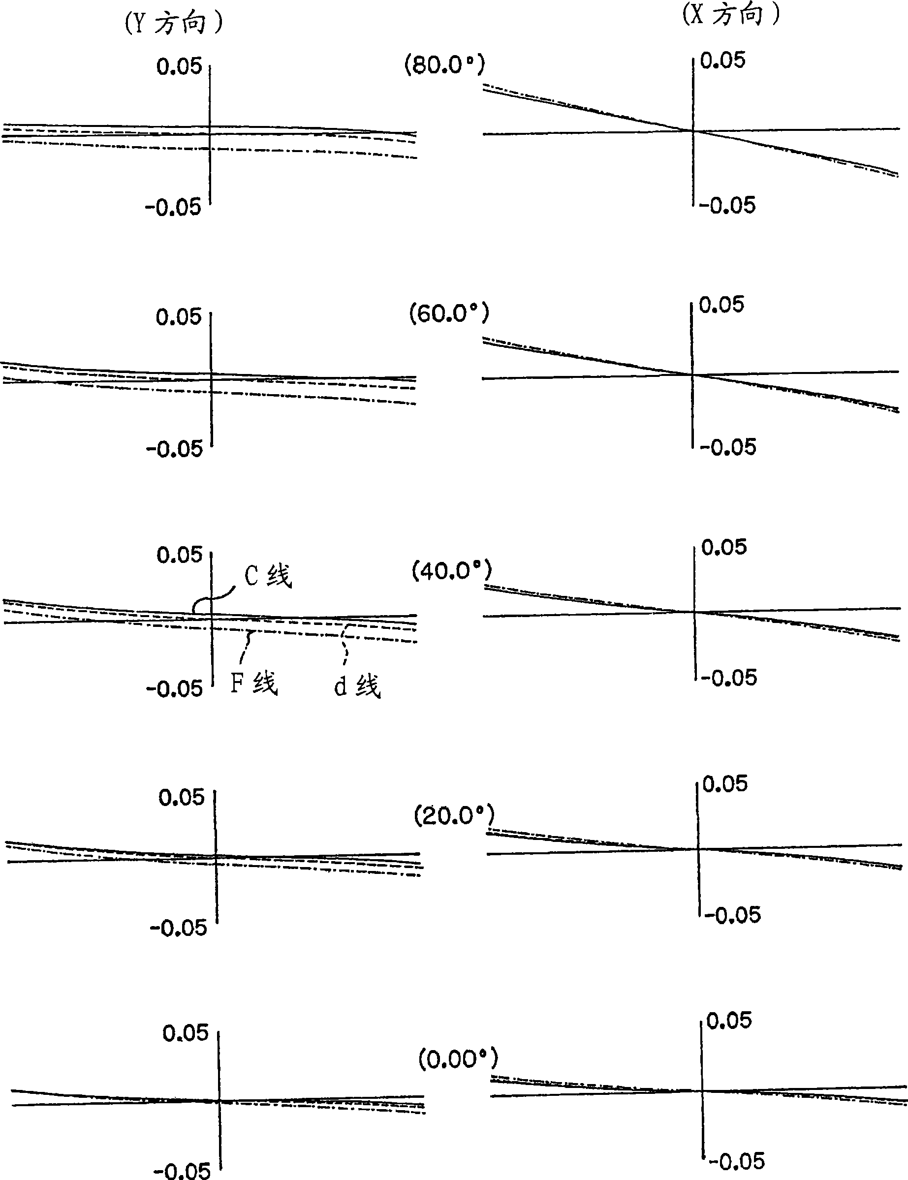
[0048] In addition, since the magnification factor of the meridional section is negative and the magnification factor of the sagittal section is 0 in the second transmission surface, astigmatism occurs. Preferably, an aspheric surface for correcting astigmatism generated on the surface is disposed on the image surface 5 side with the diaphragm 6 interposed therebetween to correct the astigmatism. More preferably, the astigmatism correction ability can be improved by arranging the aspheric surface near the image plane 5 .
[0049] More preferably, the surface for correcting astigmatism is formed by a rotationally symmetrical free-form surface having different magnifications on the sagittal plane and the meridian plane, and is arranged near the image plane. And the rotation symmetri...
PUM
Abstract
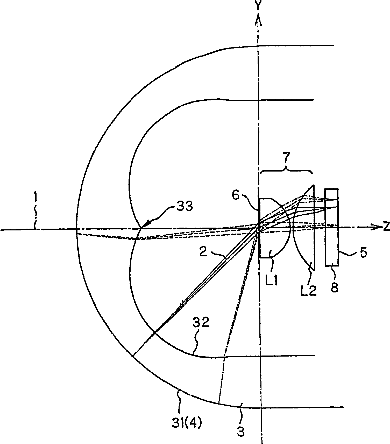
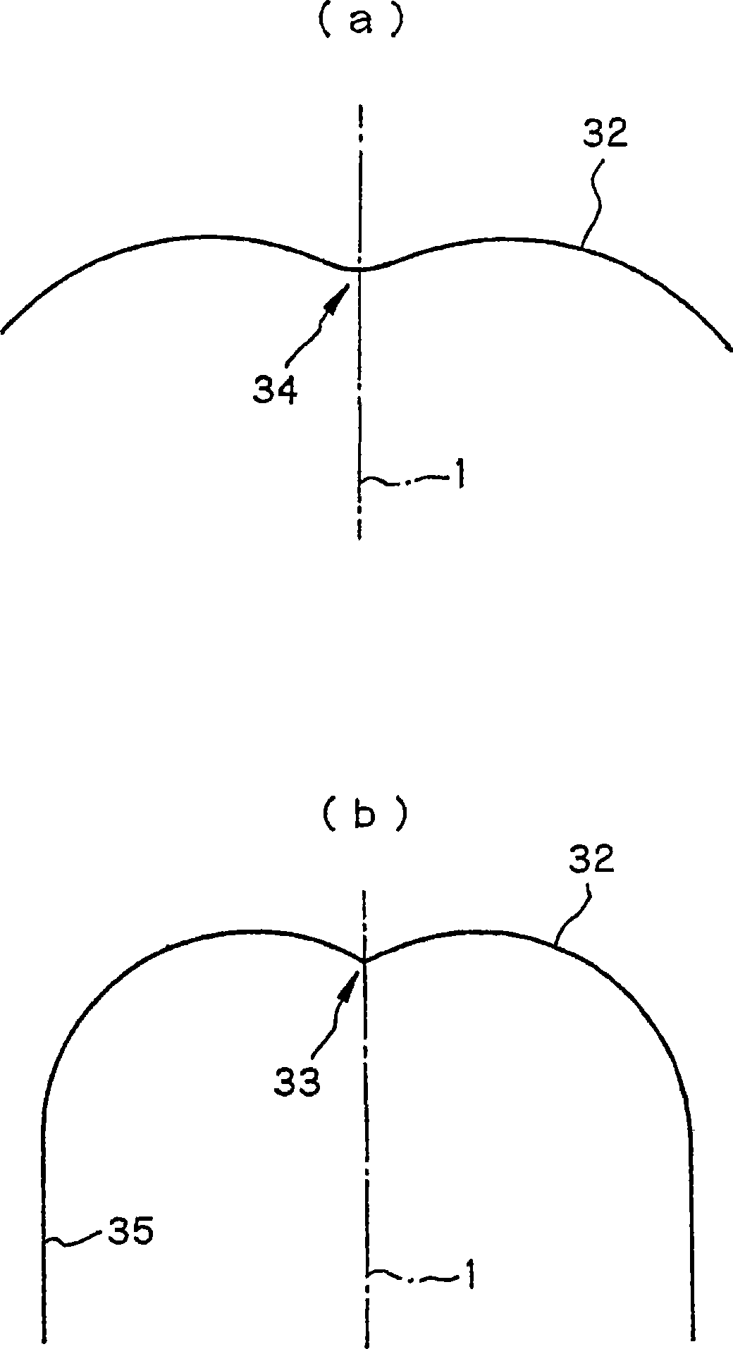
Provided is an optical system, which can pickup an image having a wide photographing field angle by a simple constitution, is small and has excellently corrected aberration and high resolution. The optical system is an imaging system for imaging a recessed object surface (4), which is rotationally-symmetric about a center axis (1), on a flat image surface (5) orthogonally intersecting with the center axis. The optical system has the refraction element (3) composed of a transparent medium provided with a first transmitting surface (31), which is rotationally-symmetric about the center axis (1) and is arranged along the object surface (4), and a second transmitting surface (32), which is rotationally symmetric about the center axis (1). The transparent medium has a refractive index larger than 1. In the optical system wherein a luminous flux from the object surface (4) is focused on the image surface (5) through the refraction element (3), the second transmitting surface (32) has a recessed surface facing the image surface (5), and a negative power is provided within a cross-section which includes the center axis (1), at a position off the center axis (1).
Description
technical field [0001] The present invention relates to an optical system, in particular to an objective optical system or an imaging optical system for forming an image of an object with a larger viewing angle on a planar ring-shaped image plane. Background technique [0002] Conventionally, a wide-angle optical system such as a fisheye lens has been used as a device for imaging a peripheral portion having a wide angle of view. However, imaging with a wide angle of view increases the number of optical system configurations, making it difficult to apply to compact optical devices, especially endoscopes and capsule endoscopes. [0003] Conventionally, Patent Document 1 proposes that the inner surface of the hemispherical transparent cover at the distal end of the capsuleendoscope is configured as a conical surface to widen the observation range, but the principle is not clear. In addition, Patent Document 2 proposes to configure the front surface of the transparent cover at...
Claims
Application Information
Patent Timeline
Application Date:The date an application was filed.
Publication Date:The date a patent or application was officially published.
First Publication Date:The earliest publication date of a patent with the same application number.
Issue Date:Publication date of the patent grant document.
PCT Entry Date:The Entry date of PCT National Phase.
Estimated Expiry Date:The statutory expiry date of a patent right according to the Patent Law, and it is the longest term of protection that the patent right can achieve without the termination of the patent right due to other reasons(Term extension factor has been taken into account ).
Invalid Date:Actual expiry date is based on effective date or publication date of legal transaction data of invalid patent.

