Numerical value control device controlling multi-shaft processor located on a cutter front point position

A numerical control device, multi-axis processing machine technology, applied in the field of positive vector, can solve the problems of unpublished calculation methods, etc.

Active Publication Date: 2012-04-04
FANUC LTD
View PDF13 Cites 17 Cited by
  • Summary
  • Abstract
  • Description
  • Claims
  • Application Information

AI Technical Summary

Problems solved by technology

[0004] Japanese Patent Laid-Open No. 2009-110083 (corresponding to German Laid-open Publication DE102008043182A1) discloses a technology that may be equivalent to the technology described in the aforementioned Japanese Patent Laid-Open No. 57-73409 and Japanese Patent Laid-Open No. 57-75309. technology, but did not disclose specific calculation methods, etc.

Method used


Image

  • Numerical value control device controlling multi-shaft processor located on a cutter front point position
  • Numerical value control device controlling multi-shaft processor located on a cutter front point position
  • Numerical value control device controlling multi-shaft processor located on a cutter front point position

Examples


Embodiment Construction

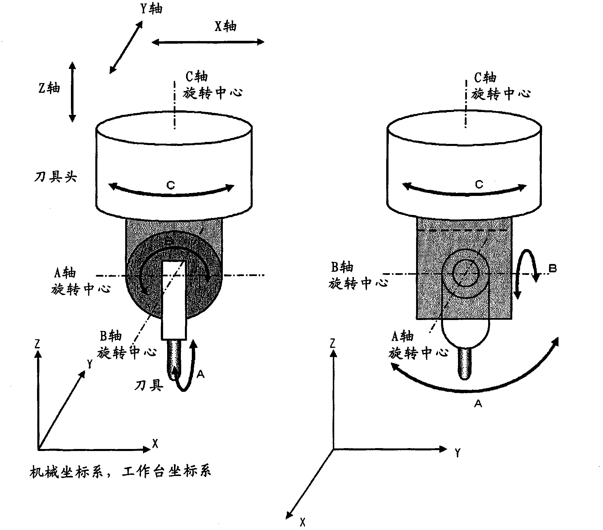
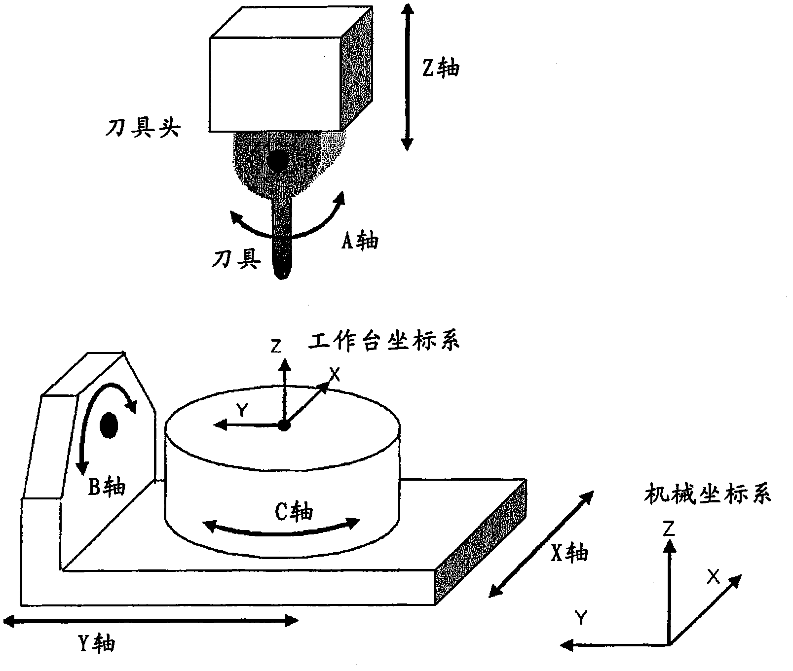
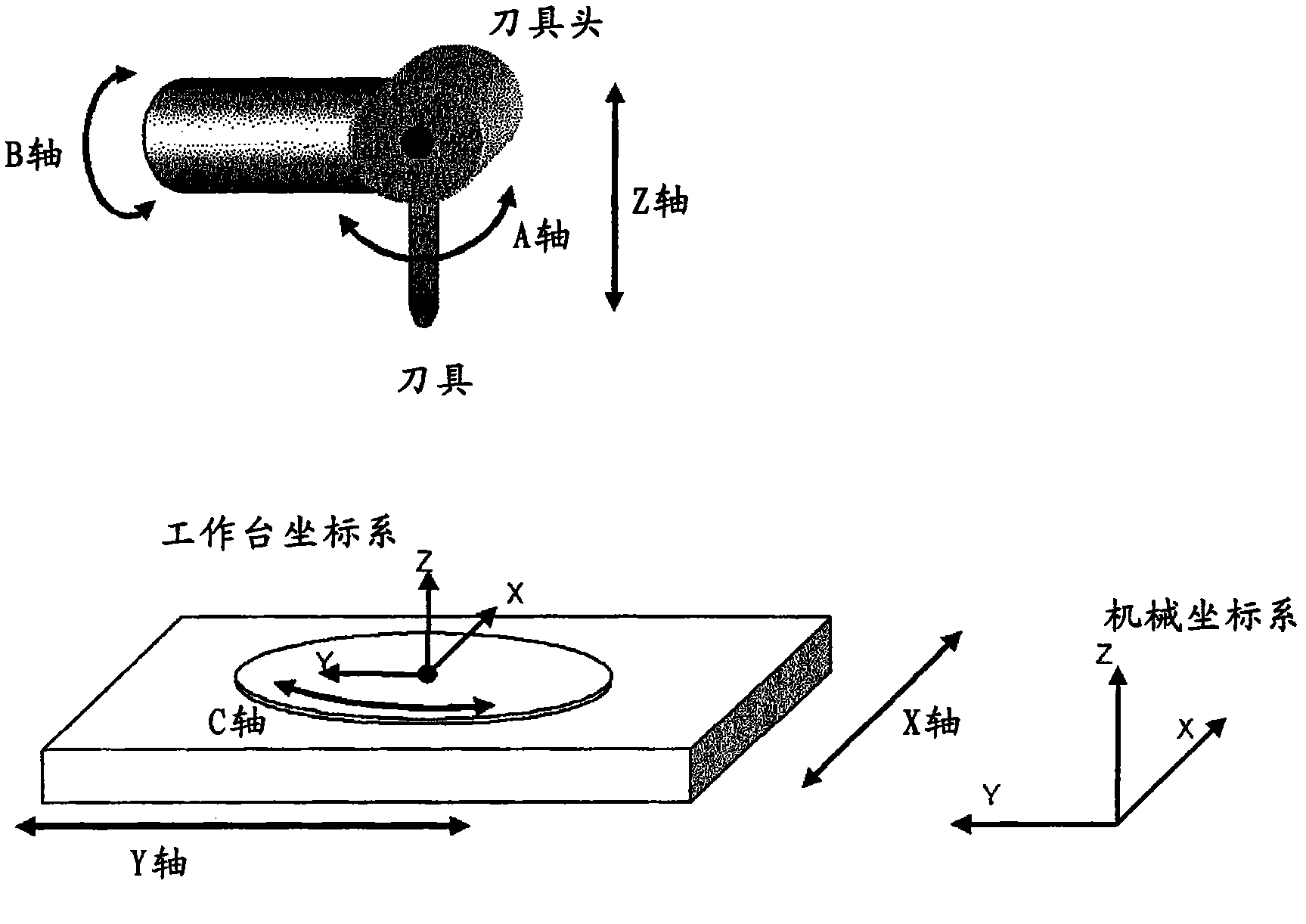
[0034] The multi-axis processing machine controlled by the numerical control device of the present invention processes a workpiece (processed object) mounted on a table with at least three linear axes and at least three rotary axes. During automatic operation, the numerical controller controls the three linear axes and the three rotary axes of the multi-axis processing machine so that the actual position of the tip of the tool becomes the position of the tip of the tool commanded by the program. In addition, the numerical control device can shift the position of the tool tip point or the tool length correction vector during the movement of the rotary axis by the manual move command while maintaining the position of the tool tip point during the linear axis movement by the manual move command.

[0035] Here, the manual movement command includes the overlapping of the manual movement command in the automatic operation and the control of the three linear axes and the three rotatio...


PUM


Abstract

The invention provides a numerical value control device, which controls a multi-shaft processor having three linear shafts and three rotary shafts. A path on a cutter front point is instructed and interpolated on a workbench coordinate system. The rotary shafts are meanwhile instructed and interpolated. According to the linear shaft position, the rotary shaft position of the interpolated cutter front point position and the cutter length rectified vector, the linear shaft position and the rotary shaft position of the control points as the mechanism coordinate system are calculated. Then the linear shafts and the rotary shafts are driven to obtain the position.

Description

technical field [0001] The present invention relates to a numerical control device for controlling a multi-axis processing machine having at least three linear axes and three rotary axes. In particular, it relates to a numerical control device for commanding and interpolating a rotation axis while commanding and interpolating a path of a tool tip point on a table coordinate system defined on the table and moving along with the movement of the table, and Calculate the position of the linear axis and the rotary axis as the control point of the machine coordinate system based on the position of the linear axis, the position of the rotary axis and the tool length correction vector after interpolation, and drive the linear axis and the rotary axis to The locations of these finds. It also relates to a linear axis movement that can be manually commanded (handle feed, jog feed, etc.) by adding the interpolated tool tip position, tool length correction vector, or rotary axis position ...

Claims


Application Information

Patent Timeline
Patent Type & Authority Applications(China)
IPC IPC(8): G05B19/409
CPCG05B19/404G05B19/41G05B2219/50289
Inventor 大槻俊明井出聪一郎花冈修
Owner FANUC LTD
Why Eureka
Try Eureka