
Capacitive charging current control circuit

A current control circuit, capacitor charging technology, applied in battery circuit devices, circuit devices, current collectors, etc., can solve problems such as bad loss, adverse effects of normal operation of the chip 104, large loss, etc.

Active Publication Date: 2012-04-04
NATIONZ TECH INC
View PDF4 Cites 6 Cited by
  • Summary
  • Abstract
  • Description
  • Claims
  • Application Information

AI Technical Summary

Problems solved by technology

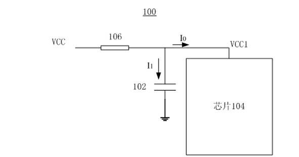
Although such a technical solution can achieve a certain effect, it has two disadvantages: first, the larger the filter capacitor 102, the larger the required current-limiting resistor 106, if the current-limiting resistor 106 is too large, the chip 104 Actual power supply voltage VCC1=VCC-I 0 * R1 becomes smaller, which will cause adverse effects on the normal operation of the chip 104; secondly, after the chip 104 is normally powered on and started, the current limiting resistor 106 will bring additional bad losses, and the more the current limiting resistor 106 The greater the loss

Method used


Image

  • Capacitive charging current control circuit
  • Capacitive charging current control circuit
  • Capacitive charging current control circuit

Examples


Embodiment Construction

[0037] The detailed description of the present invention directly or indirectly expresses the operation of the technical solution of the present invention mainly through programs, steps, logic blocks, processes or other general descriptions. In the ensuing description, numerous specific details are set forth in order to provide a thorough understanding of the present invention. Rather, the invention may be practiced without these specific details. These descriptions and representations are used herein primarily to effectively convey the nature of their work to others skilled in the art. In other words, to avoid obscuring the essence of the technical solutions of the present invention, well-known methods, procedures, components and circuits are not described in detail because they are already easy to understand.

[0038] Reference herein to "one embodiment" or "an embodiment" refers to a particular feature, structure or characteristic that can be included in at least one imple...


PUM


Abstract

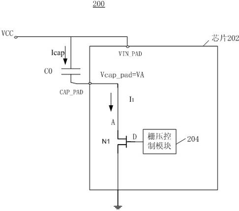
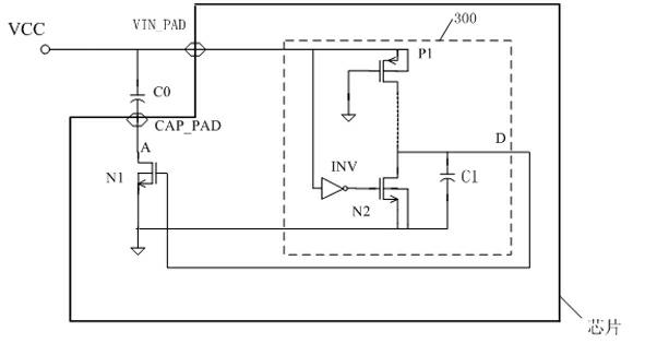
The invention provides a capacitive charging current control circuit. The circuit comprises a circuit switch, a filter capacitor and a control circuit. One end of the circuit switch is connected with the ground, a positive plate of the filter capacitor is connected with a power supply, and a negative plate of the filter capacitor is connected with the other end of the circuit switch. The control circuit is connected with a control end of the circuit switch and sends control signals to control on resistance of the circuit switch. The circuit switch controlled by gate voltage is added between the filter capacitor and ground connection, thereby achieving the aim of controlling charging current of the filter capacitor, adding no more power consumption after a chip is started normally, and being not capable of influencing working performance of the filter capacitor.

Description

technical field [0001] The invention relates to the field of chip design, in particular to a circuit for controlling the charging current of a filter capacitor. Background technique [0002] With the rapid development of digital equipment, the volume of digital equipment is getting smaller and smaller, and the functions are more and more. Correspondingly, there are stricter requirements on the power consumption and power-on current of the core component chips of these digital devices. In the prior art, in order to make the chip work more stably, it is often necessary to connect external filter capacitors to power pins and other parts outside the chip. However, in order to achieve a better filtering effect, filter capacitors with larger capacitance are often used. In specific use, it is found that the transient charging current of a larger filter capacitor is generally larger. For some chips that include a short-circuit protection mechanism for the power supply, the use...

Claims


Application Information

Patent Timeline
IPC IPC(8): H02J7/00
Inventor 石道林程珍娟
Owner NATIONZ TECH INC
Learn More