Method and system for ignition coil control

A technology of ignition coil and controller, applied in ignition controller, spark ignition controller, engine ignition, etc., can solve the problems of circuit resistance fluctuation and affecting ignition coil current, etc.

Active Publication Date: 2022-06-24
FORD GLOBAL TECH LLC
View PDF6 Cites 0 Cited by
  • Summary
  • Abstract
  • Description
  • Claims
  • Application Information

AI Technical Summary

Problems solved by technology

Changes in ignition coil temperature may cause fluctuations in circuit resistance, which in turn may affect ignition coil current

Method used


Image

  • Method and system for ignition coil control
  • Method and system for ignition coil control
  • Method and system for ignition coil control

Examples


Embodiment Construction

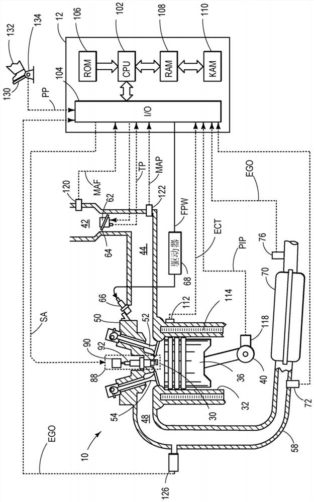
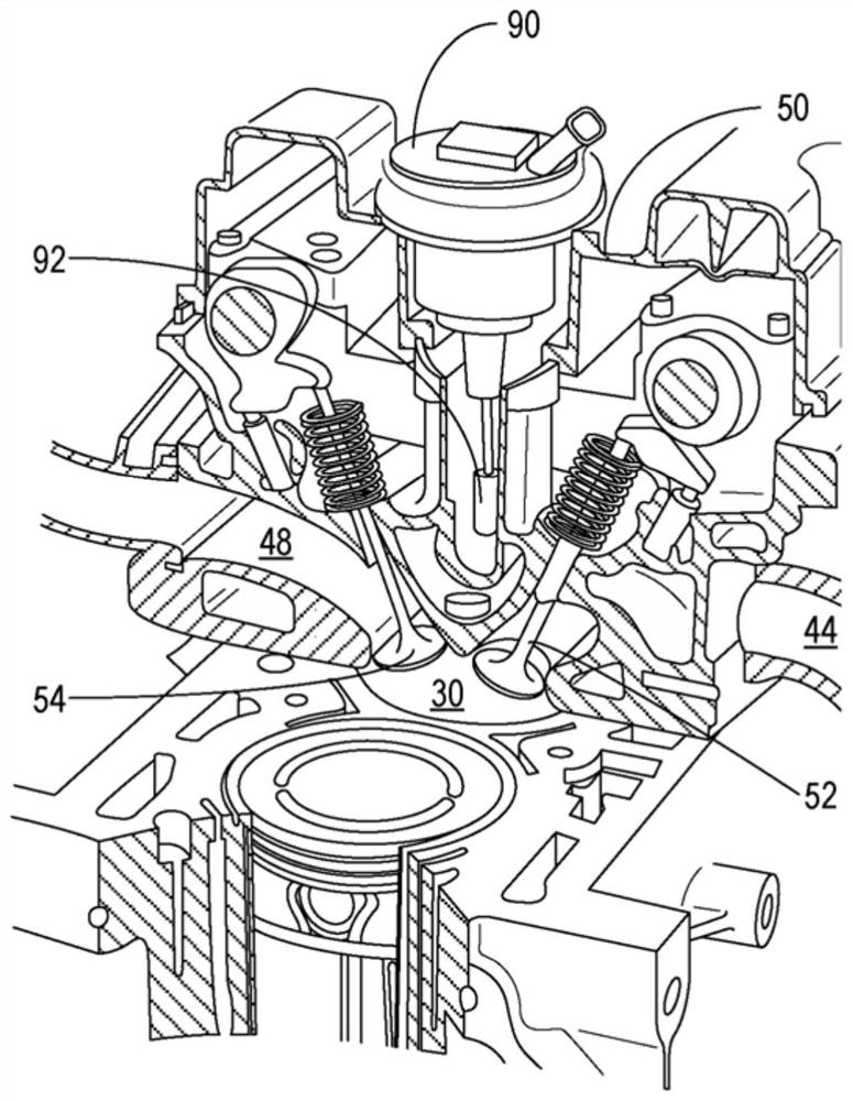
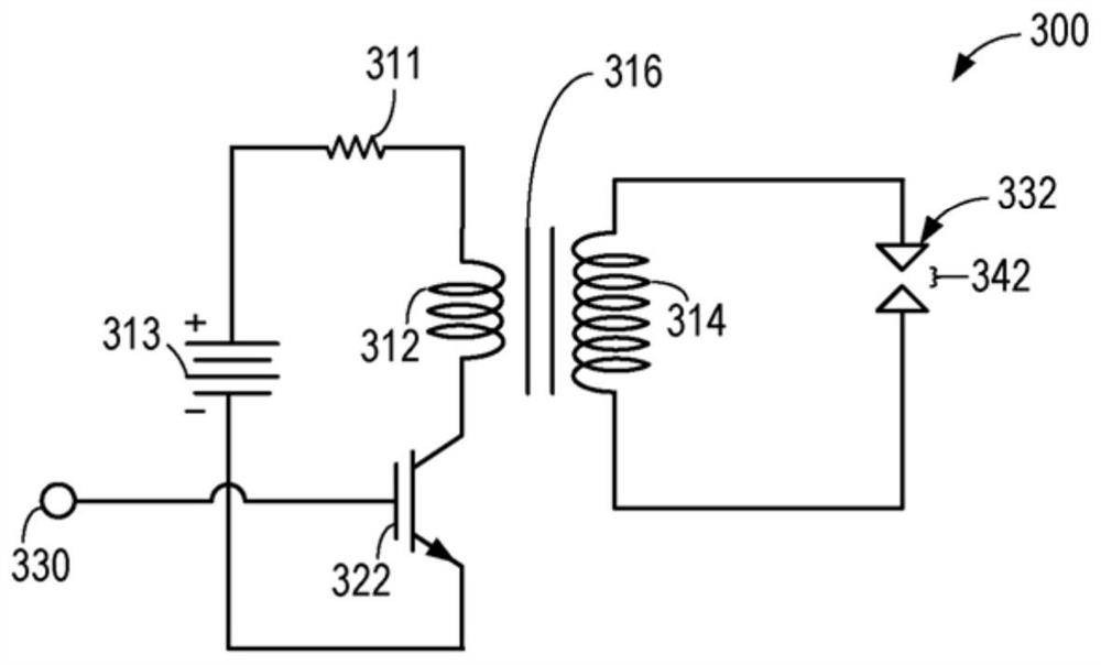
[0015] The following description relates to systems and methods for controlling current charged to an ignition coil coupled to an internal combustion engine system. exist figure 1 An example of an internal combustion engine system is shown in . figure 2 is a partial view of the engine system showing the location of the ignition system within the engine system. The ignition system may contain ignition coils and spark plugs. image 3 A simplified diagram showing the circuit of the ignition system. The circuit includes a primary coil, a battery, and a secondary coil. By coupling the primary coil to the battery for the dwell time, a charging current can be accumulated and flowed through the primary coil. The amplitude of the current depends on the ignition coil temperature. Figure 4 An example method of estimating ignition coil temperature during engine operation is shown. Figure 5 An example method of determining a dwell time based on an estimated ignition coil temperatu...


PUM


Abstract

The present application relates to methods and systems for ignition coil control. Methods and systems are provided for determining ignition coil dwell times based on estimated ignition coil temperatures. In one example, a method includes estimating an ignition coil temperature based on heat transfer between an engine and the ignition coil, heat transfer between an environment and the ignition coil, and internal resistive heating of the ignition coil.

Description

technical field [0001] The present invention generally relates to a method and system for controlling the current charged to an ignition coil by determining a dwell time based on an estimate of the ignition coil temperature. Background technique [0002] Combustion in an internal combustion engine can be initiated using an ignition spark produced by a spark plug. The ignition spark can be initiated by charging the ignition coil with a low voltage battery. The duration or dwell time of charging can determine the amplitude of the ignition coil current and thus the energy of the ignition spark. The energy of the ignition spark directly affects engine performance. For example, an ignition spark with an energy below a desired level may cause unreliable combustion or misfire. On the other hand, ignition sparks with higher than desired levels of energy may increase losses in the ignition system. [0003] Other attempts to address the ignition coil control problem include contro...

Claims


Application Information

Patent Timeline
Patent Type & Authority Patents(China)
IPC IPC(8): F02P3/045F02P9/00
CPCF02P3/045F02P9/002F02P17/10F02P3/0456F02P9/00
Inventor J·卡特赖特K·普莱
Owner FORD GLOBAL TECH LLC
Why Eureka
Try Eureka