
Method and system for realizing intelligent monitoring

A technology of intelligent monitoring and implementation methods, applied in transmission systems, digital transmission systems, electrical components, etc., can solve the problem of inability to judge the load balance of back-end nodes, inability to realize flexible calls between large-scale resources, and inability to monitor the internal performance of services and services. Availability and other issues, to achieve the effect of flexible invocation

Active Publication Date: 2012-04-04
CHINA MOBILE GRP FUJIAN CO LTD
View PDF3 Cites 8 Cited by
  • Summary
  • Abstract
  • Description
  • Claims
  • Application Information

AI Technical Summary

Problems solved by technology

[0004] It can be seen that the existing load balancer technology is mainly based on the activity of the network port and the custom monitoring script on the node for monitoring, which cannot monitor the internal performance of the business and the availability of the business
Moreover, the existing load balancer technology cannot give a comprehensive load balancing judgment based on the overall operation of the back-end nodes, and cannot realize flexible calls between large-scale resources

Method used


Image

  • Method and system for realizing intelligent monitoring
  • Method and system for realizing intelligent monitoring
  • Method and system for realizing intelligent monitoring

Examples


Embodiment 1

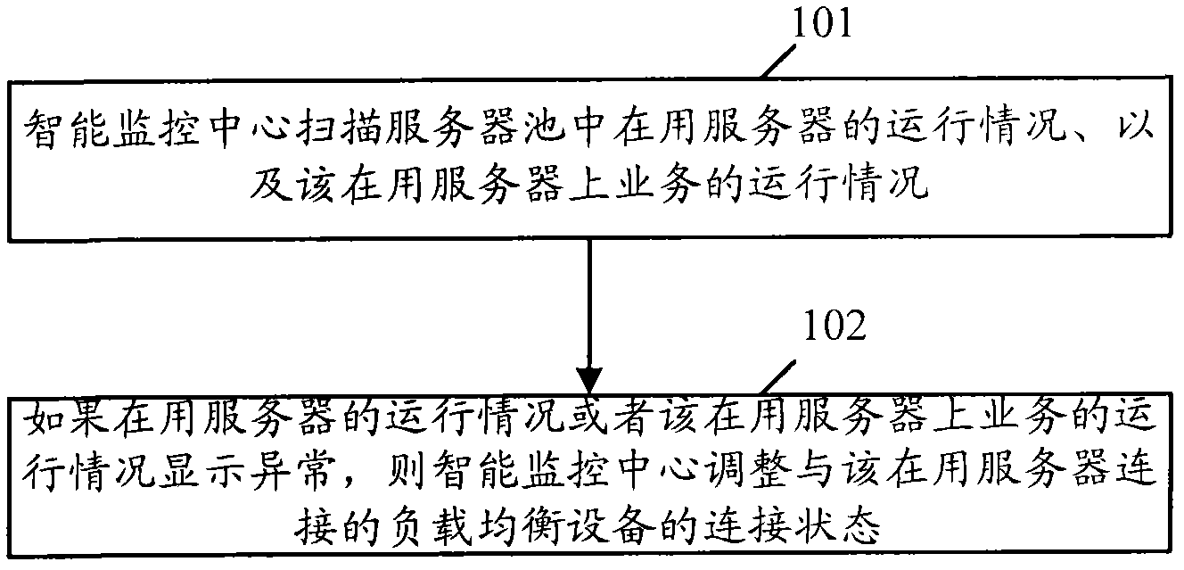
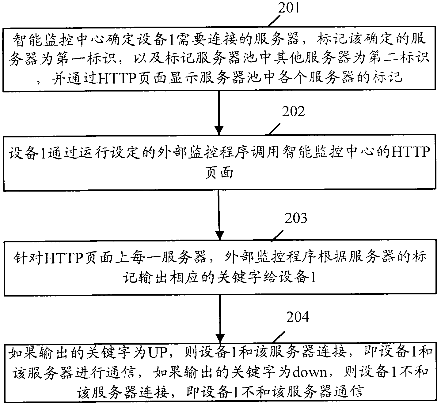
[0066] The first embodiment is described by taking the abnormal display of the running status of the server in use as an example. If the intelligent monitoring center scans in the above step 101 that the operation of the server in use such as server 1 is abnormal, then it is necessary to adjust the connection status of the load balancing device connected to the server 1 such as device 1 . As for how the intelligent monitoring center adjusts the connection state of the device 1, it will be described below.

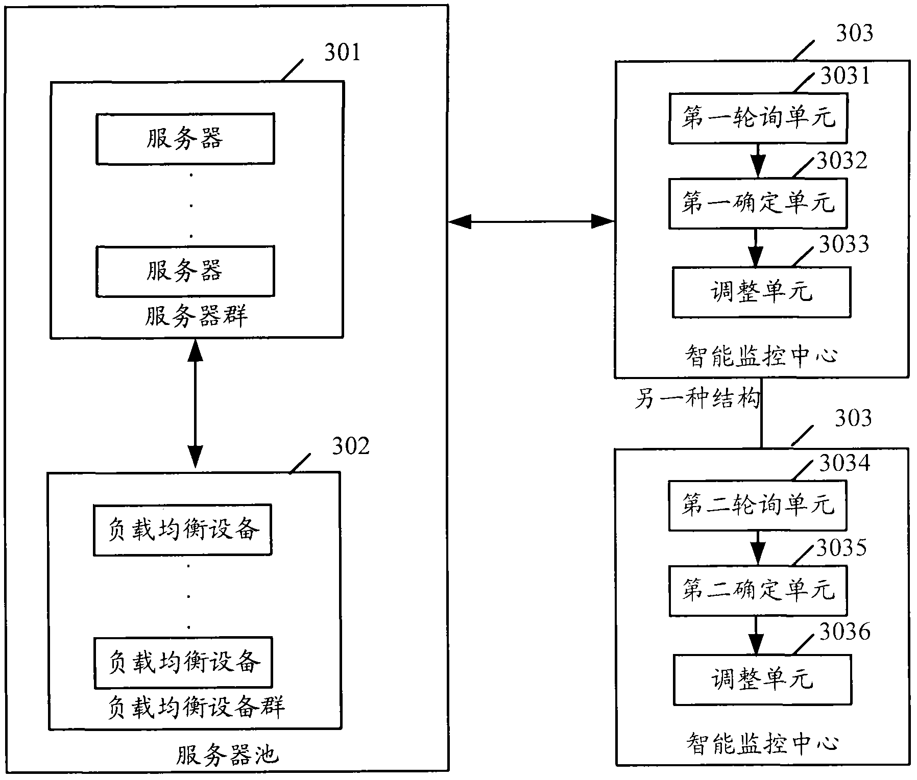
[0067] When the alarm indicator of server 1 shows abnormality, the intelligent monitoring center first polls the standby server according to the priority order of the standby server (the priority of the standby server is set by the user in advance according to the actual situation), so as to poll for the server to take over 1 working server. Of course, if all the backup servers are polled, but no backup server to take over the work of the server 1 is found, a new server ca...

Embodiment 2

[0084] The second embodiment is described by taking the abnormal display of the running status of the service on the active server as an example. If the intelligent monitoring center scans in the above step 101 that the operation of the service such as service 1 on the server such as server 1 is abnormal, then the connection status of the load balancing device connected to the server 1 such as device 1 needs to be adjusted. As for how the intelligent monitoring center adjusts the connection state of the device 1, it will be described below.

[0085]When the alarm indicator of service 1 on server 1 shows abnormality, the intelligent monitoring center first polls the standby servers according to the priority order of the standby servers, so as to poll the servers that can run service 1. Of course, if no server capable of running service 1 is found after polling all standby servers, a new server may be added, and the newly added server may be determined as the server for running ...


PUM


Abstract

The invention provides a method and a system for realizing intelligent monitoring, wherein a server group and a load balance device group are connected to form a server pool; the method comprises the steps that A, an intelligent monitoring centre scans the operation condition of the server employed by the server pool and the operation condition of the service on the server; and B, if the operation condition of the server or the operation condition of the service on the server is abnormal, the intelligent monitoring centre regulates the connection state of the load balance device connected with the server. According to the invention, the service performance and usability can be monitored and flexible calling among large-range resources can be realized.

Description

technical field [0001] The invention relates to monitoring technology, in particular to a method and system for realizing intelligent monitoring. Background technique [0002] At present, the service support network has gradually developed from a concept to a real physical network, showing more and more obvious "network" characteristics. In the service support network, the high availability and concurrent processing capabilities that can be realized are mainly the load balancer technology. [0003] The load balancer technology is based on the existing network structure, which requires the installation of a load balancing device between the server and the external network, and the load balancing strategy and intelligent traffic management are implemented by the dedicated device, the load balancer. Specifically: the load balancer distributes a large amount of concurrent access or data traffic to multiple nodes such as servers for separate processing, and conducts real-time mo...

Claims


Application Information

Patent Timeline
IPC IPC(8): H04L12/26H04L12/24H04L12/56H04L12/803
Inventor 彭家华林志云赵智勇陈翔宇刘良军
Owner CHINA MOBILE GRP FUJIAN CO LTD
Learn More