
Microwave irradiation device and microwave irradiation method

一种微波照射、波形的技术,应用在微波加热、电热装置、可持续建筑等方向,能够解决反射波增多、增加功率等问题,达到电场均一性提高、增加微波功率、增加电场强度的效果

Active Publication Date: 2012-04-04
TOKYO ELECTRON LTD
View PDF4 Cites 10 Cited by
  • Summary
  • Abstract
  • Description
  • Claims
  • Application Information

AI Technical Summary

Problems solved by technology

However, when microwaves are synthesized using multiple magnetrons, if microwaves from multiple magnetrons are irradiated simultaneously, unlike the case of combining them in a plasma state, electromagnetic waves (microwaves) interfere with each other and reflect each other. increase, it is difficult to effectively increase the power

Method used


Image

  • Microwave irradiation device and microwave irradiation method
  • Microwave irradiation device and microwave irradiation method
  • Microwave irradiation device and microwave irradiation method

Examples


Embodiment Construction

[0051] Hereinafter, an embodiment of the present invention will be described in detail with reference to the drawings. Here, an example in which the present invention is applied to an apparatus that uses a semiconductor wafer as an object to be processed and performs annealing by irradiating microwaves will be described. However, the object to be processed is not limited to semiconductor wafers, and of course, the treatment by irradiating microwaves is not limited to annealing.

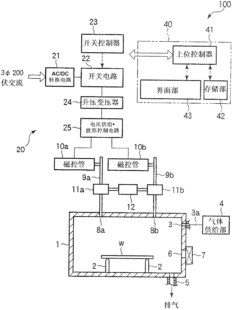
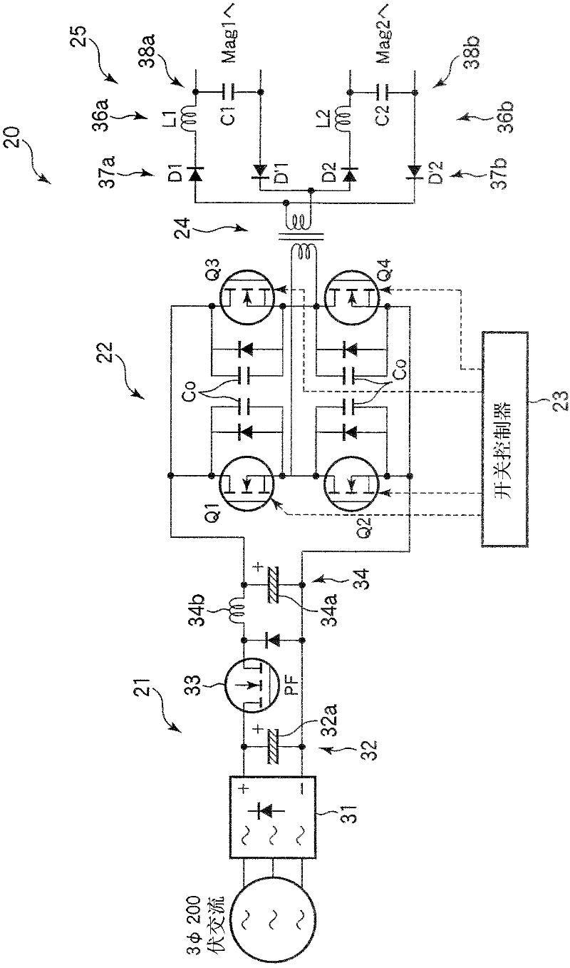
[0052] figure 1 It is a schematic diagram showing a microwave irradiation device according to one embodiment of the present invention. This microwave irradiation apparatus 100 has a chamber 1 for accommodating a semiconductor wafer W as an object to be processed. In the chamber 1 , a plurality of, for example, three (only two are shown in the figure) mounting pins 2 on which the semiconductor wafer W is mounted are provided so as to protrude from the bottom of the chamber 1 . The mounting pin 2 is ...


PUM


Abstract

The present invention aims at providing a microwave irradiation device and a microwave irradiation method for using a plurality of magnetrons to reduce reflection electricity thereby illuminating microwave. The microwave irradiation device includes a chamber 1 for accommodating an object to be processed; a plurality of magnetrons 10a and 10b for generating microwaves and irradiating the microwaves to the object to be processed in the chamber; and a power supply unit 20 for supplying a pulse-shaped voltage to each magnetron. The power supply unit supplies the pulse-shaped voltage to the magnetrons while preventing temporal overlap of voltage pulses of the pulse-shaped voltage supplied to the respective magnetrons with each other.

Description

technical field [0001] The present invention relates to a microwave irradiation device and a microwave irradiation method for irradiating an object with microwaves for heating or the like. Background technique [0002] In the manufacturing process of semiconductor devices, an annealing treatment is performed to activate dopants, etc., but there is a method of microwave annealing as such annealing (for example, Patent Document 1). Microwave annealing has less impurity diffusion and can form a shallow active layer, so it has attracted attention as a next-generation annealing technology. It has been reported that lattice defects can also be repaired in the case of microwave annealing. [0003] patent documents [0004] Patent Document 1: Japanese National Publication No. 2009-516375 [0005] The problem to be solved by the invention [0006] A microwave generator is generally equipped with a magnetron, and when a wafer of 300 mm is to be annealed, the power is insufficient ...

Claims


Application Information

Patent Timeline
Patent Type & Authority Applications(China)
IPC IPC(8): H05B6/64H05B6/66H01L21/67H01L21/268
CPCH05B2206/04H01L21/67115H05B6/68H01L21/324H05B6/806Y02B40/00H01L21/22
Inventor 河西繁芦田光利
Owner TOKYO ELECTRON LTD
Learn More