Radar sensors, especially lca sensors, for motor vehicles
A technology of radar sensor, motor vehicle, applied in the field of radar sensor
- Summary
- Abstract
- Description
- Claims
- Application Information
AI Technical Summary
Problems solved by technology
Method used
Image
Examples
Embodiment Construction
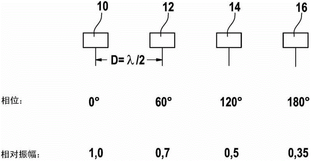
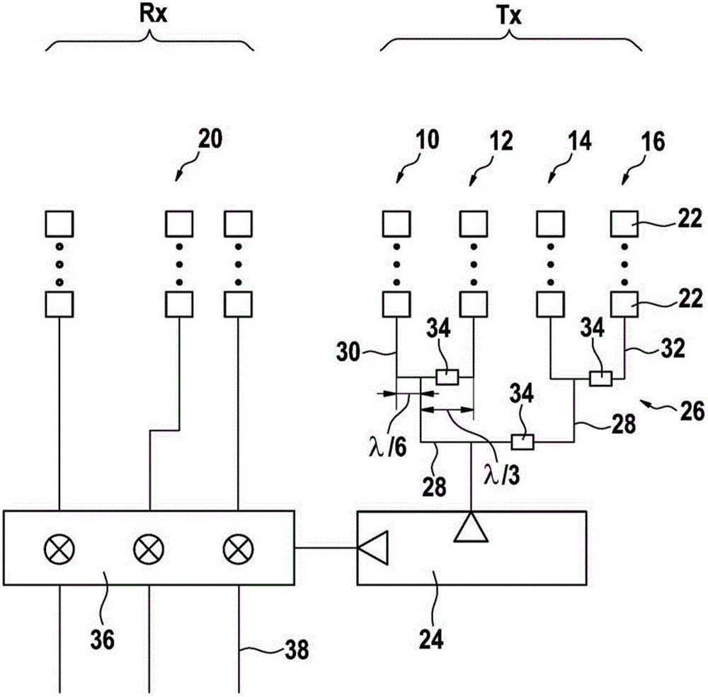
[0014] in figure 1 4 antenna elements 10, 12, 14, 16 are shown in, which are arranged in horizontal rows on an HF substrate not shown at uniform intervals. The antenna elements are represented here as individual patches. Through the feed network described in detail later, the antenna elements receive microwave signals, which should then be emitted as a radar beam. The center distance d of the antenna element is half the wavelength of the microwave beam in the example shown (d=λ / 2).
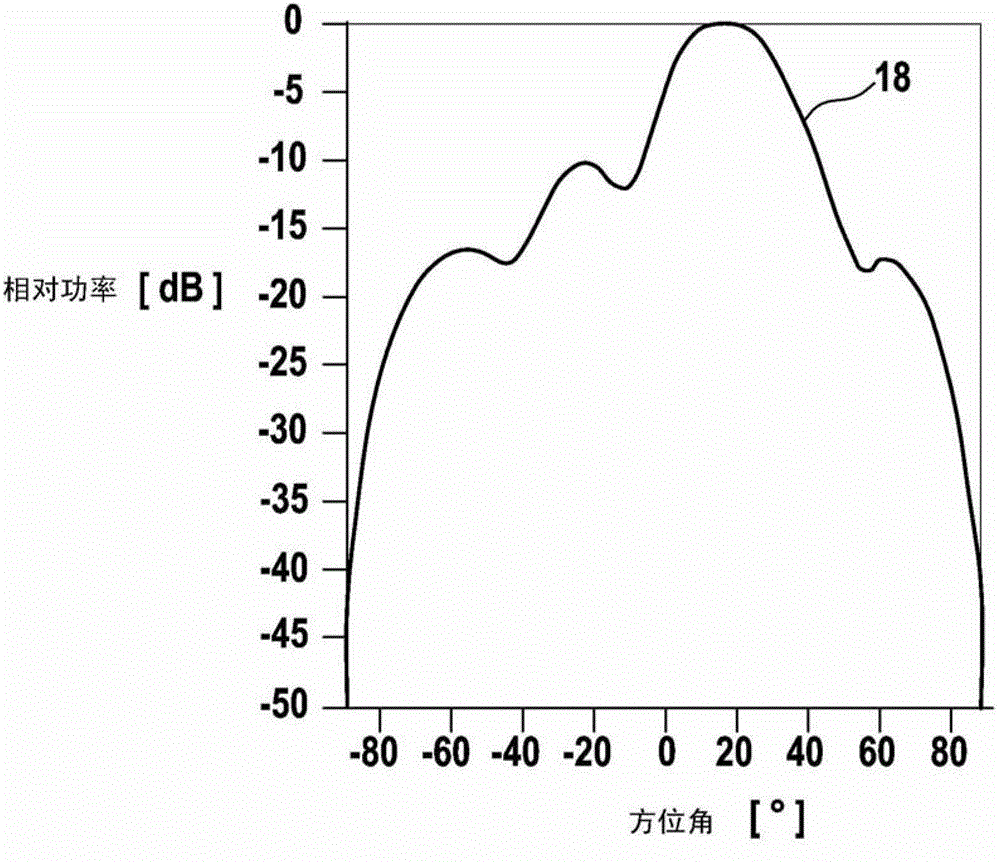
[0015] Same in figure 1 The phase distribution and amplitude distribution of the antenna elements 10, 12, 14, 16 are described in. Referring to the antenna element 10 (phase=0°) at the left end of the row, the second antenna element 12 has a phase shift of 60°, the third antenna element 14 has a phase shift of 120°, and the fourth antenna element 16 has a phase shift 180. The phase shift is therefore increased by the same increment (60°), and the antenna elements 10 and 16 at the opposite ends of ...
PUM
 Abstract
Description
Claims
Application Information
 - R&D
- Intellectual Property
- Life Sciences
- Materials
- Tech Scout
- Unparalleled Data Quality
- Higher Quality Content
- 60% Fewer Hallucinations
Browse by: Latest US Patents, China's latest patents, Technical Efficacy Thesaurus, Application Domain, Technology Topic, Popular Technical Reports.
© 2025 PatSnap. All rights reserved.Legal|Privacy policy|Modern Slavery Act Transparency Statement|Sitemap|About US| Contact US: help@patsnap.com


