Element installing device

A technology for installing devices and components, applied in the direction of electrical components, electrical components, etc., to achieve the effect of reducing the number of negative pressure sources and preventing components from falling off

Active Publication Date: 2012-04-04
YAMAHA MOTOR CO LTD
View PDF6 Cites 10 Cited by
  • Summary
  • Abstract
  • Description
  • Claims
  • Application Information

AI Technical Summary

Problems solved by technology

Therefore, in the component mounting device in which a plurality of suction nozzles are mounted on the nozzle base, the increase in t

Method used


Image

  • Element installing device
  • Element installing device
  • Element installing device

Examples


Embodiment Construction

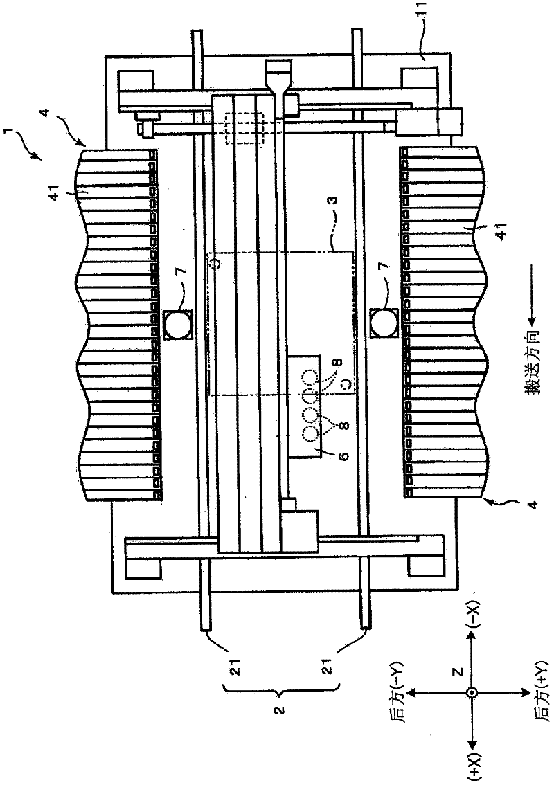
[0059] figure 1 It is a plan view showing the schematic structure of the first embodiment of the component mounting apparatus according to the present invention. In addition, in figure 1 In the drawings described later, XYZ rectangular coordinate axes are used to clarify the directional relationship among the respective drawings. In the XYZ rectangular coordinates, the conveyance direction of the substrate is defined as the X direction, the downstream side in the conveyance direction is indicated by (+), and the upstream side is indicated by (-). In addition, the direction perpendicular to the X direction in plan view is defined as the Y direction, the front is indicated by (+), and the rear is indicated by (-). Furthermore, the up-and-down direction is defined as the Z direction, the upper side is indicated by (+), and the lower side is indicated by (-).

[0060] In this component mounting apparatus 1 , a substrate transport mechanism 2 is provided on a base 11 to transp...


PUM


Abstract

The invention provides an element installing device, which has a suction nozzle seat (51) embedded into a through hole of a cylindrical part (52) and supported by the cylindrical part (52). A nozzle (83) is retained in a way to freely move along the axial direction (Z direction) relative to the retaining hole equipped inside the suction nozzle seat (51). The nozzle (83) is provided with two communication holes (FH1. FH2). Two communication holes (CH1, CH2) are also equipped inside the suction nozzle seat (51). The communication and connection of the communication holes are switched through the descending of the nozzle toward the element absorbing postion and the rising of the nozzle towards the rising end. The air pressure located on the front of the nozzle (83) and supplied from an air pressure guiding channel (831) is adjusted.

Description

technical field [0001] The present invention relates to a component mounting device which switches the pressure supplied to the suction nozzle according to the lifting operation of the suction nozzle, and uses the suction nozzle to suck a component, and mounts the sucked component on a substrate. Background technique [0002] As a component mounting apparatus having a mechanism for switching and supplying the suction nozzle pressure in accordance with the lifting operation of the suction nozzle, for example, a device described in Patent Document 1 is known. In the device described in Patent Document 1, a plurality of nozzles are provided so as to be movable up and down at predetermined intervals with respect to a horizontally rotatable nozzle holder along the rotation direction thereof. In addition, a negative pressure spool valve and a positive pressure spool valve are respectively provided for each suction nozzle on the nozzle seat. The negative pressure channel that supp...

Claims


Application Information

Patent Timeline
IPC IPC(8): H05K13/04
Inventor 稻垣重义
Owner YAMAHA MOTOR CO LTD
Why Eureka
Try Eureka