Improvements in methods for producing lens arrays

A lens array and small lens technology, applied in the field of lens arrays, can solve problems such as loss of image contrast and blurring

Inactive Publication Date: 2012-04-04
CCL SECURE PTY LTD
View PDF7 Cites 18 Cited by
  • Summary
  • Abstract
  • Description
  • Claims
  • Application Information

AI Technical Summary

Problems solved by technology

However, an arbitrary defocus design of this nature is unsuitable for multiplexed lens ima

Method used


Image

  • Improvements in methods for producing lens arrays
  • Improvements in methods for producing lens arrays
  • Improvements in methods for producing lens arrays

Examples


example

[0166] See Figure 16 An example of a printed interlaced image 900 is shown here, which is used to produce a binary "flipping image" effect when paired with a suitable lens array. In the example shown, the image elements are black image elements in the form of stripes 901 interlaced with white image elements in the form of stripes 902. In this case, the black stripes are formed by black ink printed on a transparent layer or a layer of white ink, so that the white stripes are formed by transparent areas without ink or white ink without black ink applied. When viewed through a lens array having a plurality of micro-cylindrical lenses 930, as a device having a combination of a lens array and image elements 901, 902 tilts with respect to the viewer about an axis parallel to the fringe direction, the Device produced from Figure 16 The switch from image 910 to image 920 shown at the upper left, in which the black and white areas are reversed.

[0167] The black and white stripes 901,...


PUM


Abstract

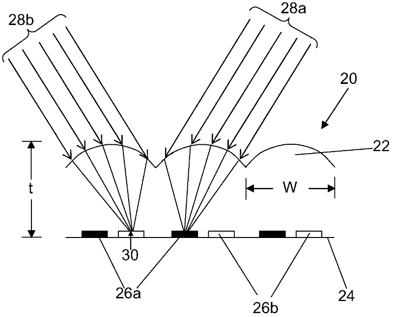
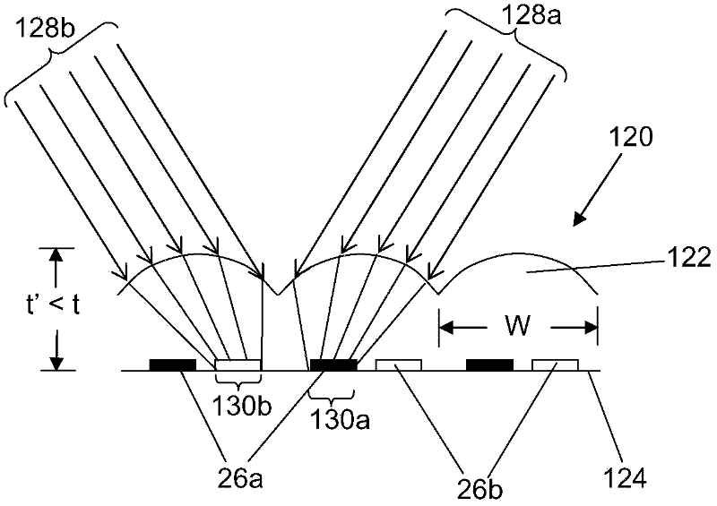
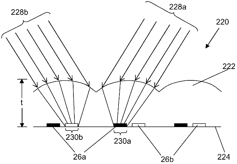
There is provided a lens array for imaging a plurality of image elements in an object plane, and a method of making a lens array. The lens array includes a plurality of lenslets formed in or on one side of a transparent or translucent material with the image elements disposed on the opposite side, and has a gauge thickness corresponding to the distance from the apex of each lenslet to the object plane. Each lenslet has a set of lens parameters. The gauge thickness and/or at least one lens parameter is or are optimised such that each lenslet has a focal point size in the object plane which is either substantially equal to the size of the image elements in the object plane, or varies from the size of the image elements by a predetermined amount.

Description

Technical field [0001] The present invention relates to improved methods for designing and manufacturing lens arrays, and to the lens arrays produced thereby. Background technique [0002] The lens array allows many different types of optical effects to be produced. For example, a lens array focused on multiple basemap elements at its focal plane can produce a three-dimensional overall image that moves, changes magnification, or deforms as the angle of view changes, or that image has The apparent depth outside the plane of this lens array. A further effect can be achieved by interweaving two or more images under the lens (e.g., in stripes under multiple cylindrical lenses) so that the viewer can see different images as the viewing angle changes. Such visual effects are useful in a variety of applications (including displays, promotional materials, collectibles) and as optically variable devices in security documents. [0003] The lens array is generally made of a transparent pol...

Claims


Application Information

Patent Timeline
IPC IPC(8): G02B27/22B42D15/10G02B3/00G02B30/27
CPCB42D2035/28G02B3/0056G02B3/005G06F17/50G02B3/0037G02B3/0012B42D15/0013B42D25/324B42D25/29G02B3/00H04N13/305B42D25/00G02B3/0006G02B30/27B42D25/351G02B30/00G02B3/0025G02B27/06G03B25/02G03B5/04B42D25/30G06F30/00
Inventor 乔纳森·A·莫恩戴维·E·罗伯茨
Owner CCL SECURE PTY LTD
Why Eureka
Try Eureka