Automatic Pedal For A Cycle With Flexible Rear Lever

A technology for bicycles and pedals, which is applied to vehicle components, crank structures, mechanical equipment, etc., and can solve problems such as heavy workload and high cost

Active Publication Date: 2012-04-11
LOOK CYCLE INT
View PDF9 Cites 3 Cited by
  • Summary
  • Abstract
  • Description
  • Claims
  • Application Information

AI Technical Summary

Problems solved by technology

[0004] The applicant company therefore proposes to omit the threads of the holes in the pedal body, which are used to fix th

Method used


Image

  • Automatic Pedal For A Cycle With Flexible Rear Lever
  • Automatic Pedal For A Cycle With Flexible Rear Lever
  • Automatic Pedal For A Cycle With Flexible Rear Lever

Examples


Embodiment Construction

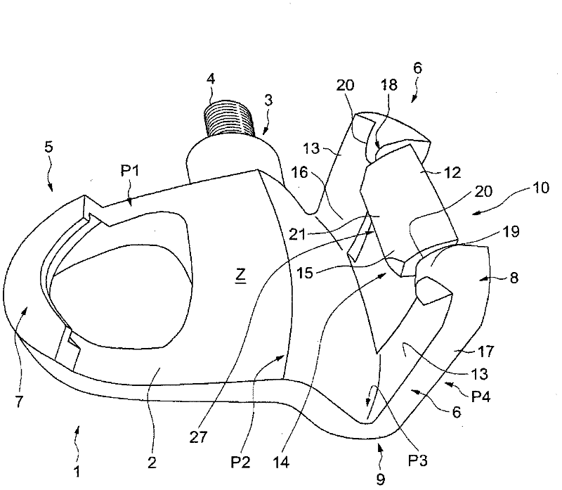
[0031] figure 1 with figure 2 An automatic pedal according to the invention is depicted, indicated by the general numeral 1, in a horizontal position corresponding to the normal position of use.

[0032] In the exemplary embodiment shown, the pedal comprises a body 2 made as a single piece. This body can be made of metal or of fiber reinforced plastic, or alternatively of carbon fibre. However, any other material suitable for the intended use may be used. However, it would of course not depart from the scope of the invention if the body 2 were made in multiple parts.

[0033] It can be seen that the body 2 includes a transverse hole 3 for mounting a spindle 4 to connect the pedal 1 to a pedal crank ( figure 1 ).

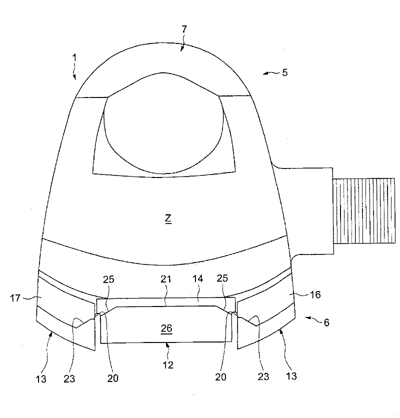
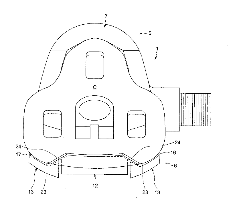
[0034] The body 2 includes a first end 5 forming a front end, and a second end 6 forming a rear end.

[0035] The body 2 comprises at the front end first attachment means 7 made in the form of a fixed hook, and at the rear end a rod 8 , which comprises a secon...


PUM


Abstract

The pedal (1) has an elastically deformable rear lever deformed between a first position in which a wedge fixed under a cyclist's shoe is maintained between a hook and a hooking unit (10) of a monoblock pedal body and a second position in which the wedge is hooked and unhooked along respective hooking and unhooking movements. The lever comprises a deformable zone (deformed during the hooking and unhooking movements, and another deformable zone deformed during one of the hooking and unhooking movements, where the two zones have different rigidities.

Description

technical field [0001] The present invention generally relates to automatic pedals for bicycles. Background technique [0002] Conventional automatic pedals include a body disposed at the front and rear ends, said body having attachment means for holding a cleat secured to the sole of the shoe. Such pedals initially have a relatively large number of component parts. Thus, in addition to the body, automatic pedals they consist of an axle assembly for mounting the pedals to a pedal crank, a rear lever hinged to the body with an axis of rotation, and an elastic system prestressing said lever, the axle assembly comprising the shaft , rings, swivel bearings, seals, etc., and when the body is mounted on the shaft assembly, enabling the body to rotate, including a rear lever hinged to the axis of rotation, and an elastic system carrying the rear lever. For example, the elastic system can be made of metal or rubber springs, blades capable of bending a curved or buckled state, etc....

Claims


Application Information

Patent Timeline
IPC IPC(8): B62M3/08
CPCB62M3/086Y10T74/2164Y10T74/2168Y10T74/217Y10T74/2172
Inventor 朱利安·布歇法比安·德朗特
Owner LOOK CYCLE INT
Why Eureka
Try Eureka