Optical fiber preform manufacturing apparatus and optical fiber preform manufacturing method
A technology of optical fiber base material and manufacturing device, applied in the direction of manufacturing tools, glass manufacturing equipment, etc., which can solve the problems of not being able to restart manufacturing, reducing the processing capacity of the optical fiber base material manufacturing device 101, and increasing the number of bubbles in the optical fiber base material
- Summary
- Abstract
- Description
- Claims
- Application Information
AI Technical Summary
Problems solved by technology
Method used
Image


Examples
no. 1 approach
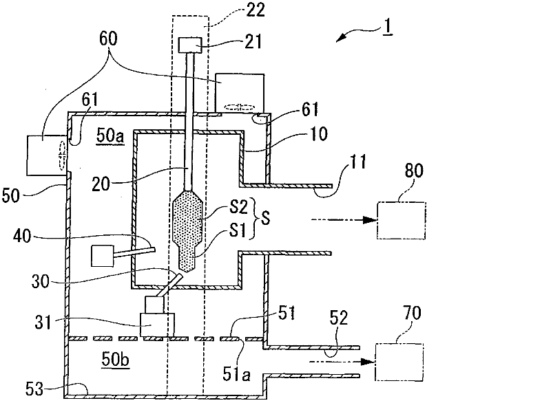
[0035] figure 1 It is a vertical cross-sectional view showing a schematic configuration of an optical fiber preform manufacturing apparatus 1 using the VAD method according to the present embodiment. in, figure 1 The up and down direction on the paper indicates the vertical direction.
[0036] Such as figure 1 As shown, the optical fiber preform manufacturing device 1 is a device for manufacturing an optical fiber porous preform S (hereinafter referred to as "porous preform S"). The optical fiber preform manufacturing device 1 includes: a reaction vessel 10, a target member 20, Core burner 30 (combustor), cladding burner 40 (combustor), chamber 50, air inlet device 60 (intake part), first exhaust device 70 (exhaust part), and second exhaust gas device 80.
[0037] The produced porous base material S is arranged inside the reaction vessel 10 . An opening (not shown) is formed in the reaction container 10 , and the space inside the reaction container 10 communicates with...
no. 2 approach
[0072] image 3 It is a vertical cross-sectional view showing a schematic configuration of an optical fiber preform manufacturing apparatus 1B using the VAD method according to the present embodiment. Also, yes image 3 neutralize figure 1 Components that are the same as those of the first embodiment shown are denoted by the same reference numerals, and description thereof will be omitted.
[0073] The core burner 30 of this embodiment is arranged on the partition plate 51 via the first support member 31 . In addition, the first support member 31 is configured to sandwich the elastic member 32 . The elastic member 32 is made of elastic rubber or resin, absorbs the vibration of the partition plate 51 when it vibrates, and suppresses the vibration of the core burner 30 .
[0074] Since a plurality of through-holes 51a are formed in the partition plate 51, the rigidity of the partition plate 51 is lower than that without the through-holes 51a. Therefore, there is a possibil...
no. 3 approach
[0077] Figure 4 It is a vertical cross-sectional view showing a schematic configuration of an optical fiber preform manufacturing apparatus 1C using the VAD method according to the present embodiment. Also, yes Figure 4 neutralize figure 1 Components that are the same as those of the first embodiment shown are denoted by the same reference numerals, and description thereof will be omitted.
[0078] The core burner 30 of this embodiment is fixed to the bottom surface 53 of the chamber 50 via the second support member 33 . The second support member 33 is formed of a plurality of rod-shaped members extending in the vertical direction, and the rod-shaped members are inserted through the through-holes 51 a of the partition plate 51 without being in contact with the through-holes 51 a of the partition plate 51 . That is, the second support member 33 is arranged on the bottom surface 53 in a state of being out of contact with the partition plate 51 .
[0079] In addition, a sp...
PUM
| Property | Measurement | Unit |
|---|---|---|
| diameter | aaaaa | aaaaa |
| length | aaaaa | aaaaa |
Abstract
Description
Claims
Application Information
 - R&D
- Intellectual Property
- Life Sciences
- Materials
- Tech Scout
- Unparalleled Data Quality
- Higher Quality Content
- 60% Fewer Hallucinations
Browse by: Latest US Patents, China's latest patents, Technical Efficacy Thesaurus, Application Domain, Technology Topic, Popular Technical Reports.
© 2025 PatSnap. All rights reserved.Legal|Privacy policy|Modern Slavery Act Transparency Statement|Sitemap|About US| Contact US: help@patsnap.com