Hydrodynamic force converter and refrigerating plant with same

A fluid power and refrigeration device technology, applied in the direction of pump devices, refrigerators, refrigeration components, etc., can solve the problems of unfavorable energy saving, large starting current, and affecting the life of the compressor, so as to achieve environmental protection and energy saving, improve service life, and avoid frequent The effect of starting and stopping

Inactive Publication Date: 2012-04-11
苏宇贵
View PDF7 Cites 0 Cited by
  • Summary
  • Abstract
  • Description
  • Claims
  • Application Information

AI Technical Summary

Problems solved by technology

However, for the fixed-frequency compressors that currently account for the vast majority, because the displacement is fixed, the cooling capacity can only be adjusted by turning on and off the refrigeration device.
As we all know, the starting current of the compressor is relatively large, frequent start and stop will affect the life of the compressor, and it is not conducive to energy saving

Method used


Image

  • Hydrodynamic force converter and refrigerating plant with same
  • Hydrodynamic force converter and refrigerating plant with same
  • Hydrodynamic force converter and refrigerating plant with same

Examples


Embodiment 1

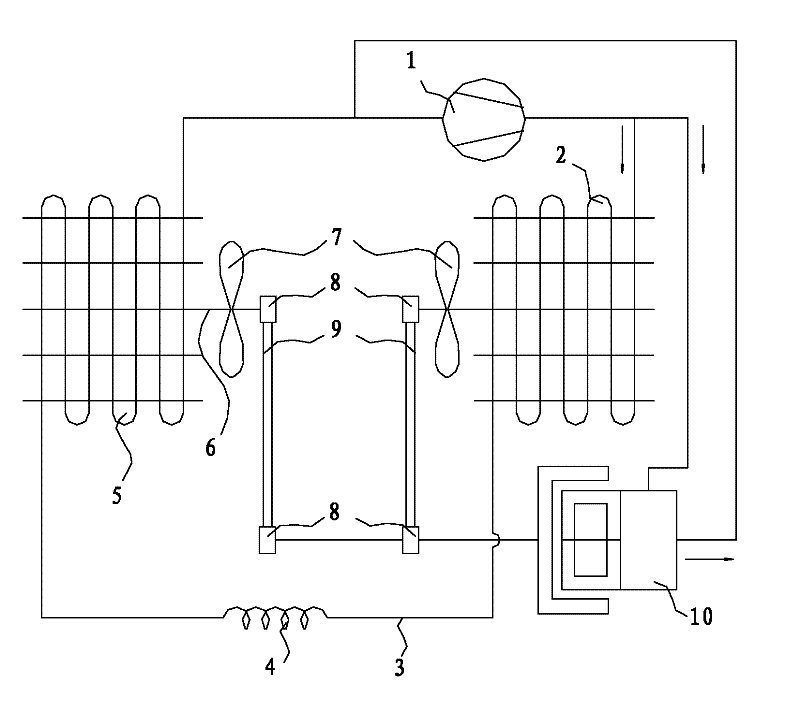
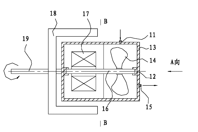
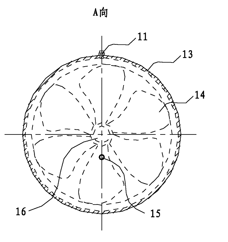
[0028] Such as Figure 1 to Figure 4 As shown, the refrigeration device includes a compressor 1, a first heat exchanger 2, a second heat exchanger 5, a throttling device 4, a system connecting pipe 3, a compressor 1, a first heat exchanger 2, a throttling device 4 and The second heat exchanger 5 is sequentially connected by the system connecting pipe 3 to form a refrigeration cycle. The refrigeration device also includes a fluid power converter 10, and the fluid power converter 10 is arranged on the cold cycle circuit. , the fluid dynamic converter 10 includes a nozzle 11, an impeller, an inner rotor magnet 17, an outer rotor magnet 18 and a driven shaft 19, the nozzle 11 is opposite to the impeller, and the impeller is fixedly connected to the inner rotor magnet 17 and placed in the cavity 13, The outer rotor magnet 18 is disposed outside the cavity 13 and corresponds to the inner rotor magnet 17 , and the driven shaft 19 is fixedly connected to the outer rotor magnet 18 . ...

Embodiment 2

[0036] Such as Figure 5 As shown, this embodiment is roughly the same as Embodiment 1, the difference is that the nozzle 11 of the fluid dynamic converter 10 communicates with the first heat exchanger 2, and the discharge port 15 and the suction port of the compressor 1 pass through the system connecting pipe 3 connected. The circulation loop formed by the fluid power converter 10, the first heat exchanger 2, and the compressor 1 is connected to the compressor 1, the first heat exchanger 2, the throttling device 4, and the second heat exchanger 5 in sequence through the system connecting pipe 3 The formed refrigeration cycle loops are connected in parallel.

Embodiment 3

[0038] Such as Figure 6 As shown, this embodiment is roughly the same as Embodiment 1, the difference is that the nozzle 11 of the fluid dynamic converter 10 communicates with the first heat exchanger 2, and the discharge port 15 of the fluid dynamic converter 10 communicates with the second heat exchanger 5 Connected through the system connection pipe 3. The circulating circuit formed by the fluid power converter 10, the first heat exchanger 2, and the second heat exchanger 5 is connected with the compressor 1, the first heat exchanger 2, the throttling device 4, and the second heat exchanger 5 through a system connecting pipe. 3 are connected in turn to form a refrigeration cycle in parallel.


PUM


Abstract

The invention discloses a hydrodynamic force converter and a refrigerating plant with the same. The hydrodynamic force converter comprises a nozzle, an impeller, an inner rotor magnet, an outer rotor magnet and a driven shaft, wherein the nozzle is opposite to the impeller; the impeller is fixedly connected with the inner rotor magnet; the inner rotor magnet is arranged inside the outer rotor magnet; and the driven shaft is fixedly connected with the outer rotor magnet. Partial unnecessary high-temperature and high-pressure gas is pumped out through a compressor of the refrigerating plant to be sprayed to the hydrodynamic force converter, the internal energy of a high-pressure, hot and humid fluid is turned to the kinetic energy of the high-pressure, hot and humid fluid during spraying, and then the kinetic energy is turned to the mechanical energy for indirectly driving a heat transfer fan to work. The frequent starting and stopping of the compressor is avoided, the dynamic configuration is simplified, the service life of the refrigerating plant is prolonged, and the environment friendliness and energy conservation are facilitated.

Description

technical field [0001] The invention relates to a fluid power converter and a refrigeration device with the fluid power converter. Background technique [0002] Most of the existing refrigerating devices are of the mechanical compression type. The motor drives the refrigerating compressor to run. The high-temperature and high-pressure refrigerant vapor from the compressor enters the condenser to release condensation heat and becomes a normal temperature and high-pressure liquid, and then enters the throttling device. The pressure is reduced, and then enters the evaporator to absorb the heat of the room to become a low-temperature, low-pressure refrigerant vapor, and then enters the compressor cycle. In general, after the refrigeration device works at full load for a period of time, the room temperature will gradually drop, and the cooling load will also decrease. To achieve the purpose of reducing the exhaust volume of the compressor to achieve energy saving. However, for ...

Claims


Application Information

Patent Timeline
Patent Type & Authority Applications(China)
IPC IPC(8): F04D25/02F25B1/00F25B41/00
Inventor 苏宇贵
Owner 苏宇贵
Why Eureka
Try Eureka