Electrowetting display devices

A technology of electrowetting and components, applied in the direction of optical components, optics, instruments, etc., can solve the problems of increasing production costs, increasing production processes, reducing the contrast and brightness of display components, etc.

Active Publication Date: 2012-04-11
IND TECH RES INST
View PDF10 Cites 13 Cited by
  • Summary
  • Abstract
  • Description
  • Claims
  • Application Information

AI Technical Summary

Problems solved by technology

[0008] However, the traditional single-layer color electrowetting display structure combines black non-polar fluid (such as ink) and color filters, part of the incident light will be absorbed by the color filters, thus reducing the contrast and brightness of the display components
Although the three-layer color stacked electrowetting display module can improve color saturation, the three-layer stacked structure not only increases the production process, but also needs to control the alignment accuracy of each layer, which will increase the production cost.

Method used


Image

  • Electrowetting display devices
  • Electrowetting display devices
  • Electrowetting display devices

Examples


Embodiment Construction

[0035] A number of different embodiments or examples are provided below to implement the features of the various embodiments of the invention. The following will briefly describe the structure and arrangement of specific embodiments. Of course, the following description is only an example, but not intended to limit the present invention. In addition, repeated component numbers may appear in each example of the present invention, but the above repetition is only used to briefly and clearly describe the present invention, and does not mean that there is a necessary relationship between various implementation examples and structures. Furthermore, a statement that a second component is formed "on" or "over" a first component may include embodiments where the first component and the second component are in direct contact, or are not in direct contact.

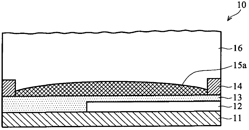
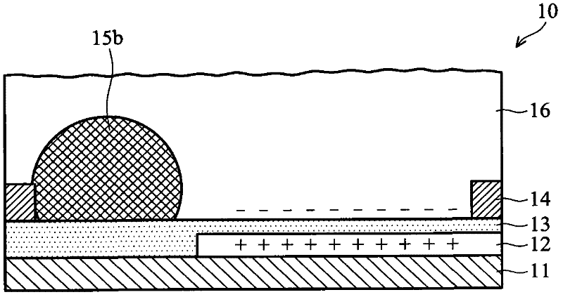
[0036]Embodiments of the present invention relate to an electrowetting display component, which performs display by changing the s...


PUM


Abstract

Electrowetting devices (EWD) are presented. The electrowetting device includes a first substrate and an opposing second substrate with a polar fluid layer and a non-polar fluid layer interposed therebetween. A first transparent electrode is disposed on the first substrate. A second electrode is disposed on the second substrate. A first partition structure is disposed on the first substrate; thereby defining a plurality of color sub-pixels. A dye and / or a pigment substance is doped in one of the polar fluid layer and the non-polar fluid layer. A luminescence substance is doped in one of the polar fluid layer and the non-polar fluid layer. An emission module (also known as an excitation module) is disposed underlying the bottom of the first substrate. The colors of the non-polar fluid layerin the neighboring sub-pixels are different.

Description

technical field [0001] The present invention relates to a display component, in particular to an electrowetting display component. Background technique [0002] Electrowetting display devices use electrowetting or electrocapillary (electrocapillary) technology to display image changes. In simple terms, the electric field effect is applied to a fluid with a free surface, so that the distribution area of ​​the fluid can be changed along the electric field effect. [0003] U.S. Patent No. 6,967,763, which is hereby incorporated by reference, discloses an electrowetting display module, wherein the polar fluid in the electrowetting display module displaces the nonpolar fluid due to the electrowetting effect, causing the nonpolar fluid to collect and / or shrink, To control the bright state and / or dark state of the pixel. [0004] Figure 1A with Figure 1B Cross-sectional views showing the voltage-off and voltage-on states of a conventional electrowetting assembly, respectively....

Claims


Application Information

Patent Timeline
Patent Type & Authority Applications(China)
IPC IPC(8): G02B26/02
CPCG02B26/005G02B26/004
Inventor 郭书玮胥智文郑惟元古昀生
Owner IND TECH RES INST
Why Eureka
Try Eureka