Multifunctional chair

A multi-functional chair and seat technology, applied to chairs, chairs with vertically adjustable seats, stools, etc., can solve the problems of single function and inability to meet the shortage of time and space, and achieve the effect of unique structure, economical and practical, and convenient use

Inactive Publication Date: 2012-04-18
张建文
6 Cites 0 Cited by

AI-Extracted Technical Summary

Problems solved by technology

[0003] The present invention aims at the problems existing in the prior art that the chair is simple in structure and single in function, especially unable to satisfy pe...

Abstract

The invention discloses a practical and multifunctional chair, which relates to medical and health care apparatuses. The chair comprises a chair seat, a chair back and chair legs; the chair seat is movably connected with the chair back through a first rotating shaft; the chair legs are movably connected with the chair seat; a first fixed part controlling the chair back to swerve to a certain position is arranged at a place where the chair seat is connected with the chair back; the chair seat comprises an upper layer and a lower layer, wherein, the upper layer is a seat plate, and the lower layer is a seat frame; the seat frame is provided with a bracing frame capable of overturning, and the bracing frame comprises a connecting rod and a footrest rack; a second rotating shaft and a second fixed part which controls the bracing frame to swerve to a certain position are arranged at a place where the bracing frame is connected with the seat frame at the lower layer of the chair seat. According to a technical scheme provided in the invention, the first rotating shaft or the second rotating shaft can freely operate; the bracing frame comprises the connecting rod and the footrest rack, which is favorable for people to put their feet at a comfortable position when they are resting on the chair or to carry out headstand; structures of the chair are beneficial for building up bodies and enable the chair to be convenient and practical to use.

Application Domain

Technology Topic

Image

  • Multifunctional chair
  • Multifunctional chair
  • Multifunctional chair

Examples

  • Experimental program(2)

Example Embodiment

[0024] Example 1
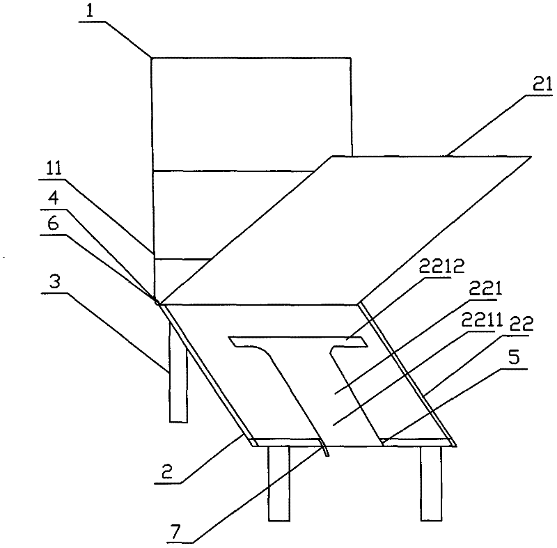
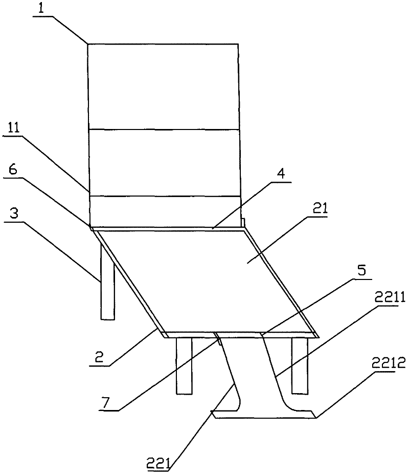
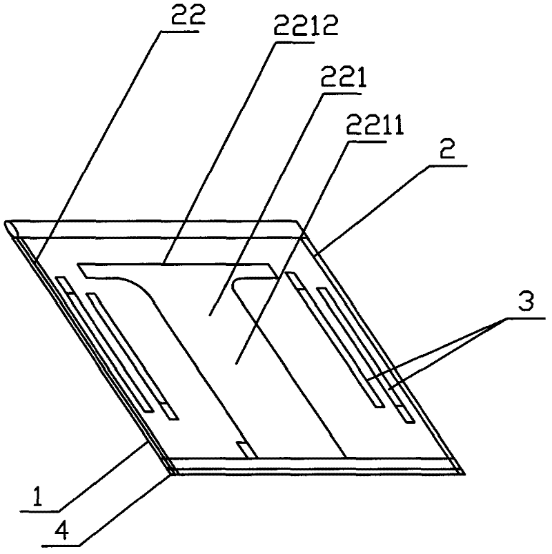
[0025] Such as figure 1 , figure 2 , image 3 , Figure 4 , Figure 5 and Figure 7 As shown, a multifunctional chair includes a chair seat 2, a chair back 1 and a chair leg 3. The chair seat 2 and the chair back 1 are movably connected by a rotating shaft 4, and the chair leg 3 and the chair seat 2 are movable Link, the connection between the seat 2 and the seat back 1 is provided with a movable nut 6 that controls the seat back 1 to turn to a certain position. The seat 2 is divided into upper and lower layers, the upper layer is the seat plate 21, and the lower layer is the seat frame 22 The seat frame 22 is provided with a reversible support frame 221. The support frame 221 includes a connecting rod 2211 and a footrest 2212. The connection between the support frame 221 and the seat frame 22 is provided with a rotating shaft 5 and a control support frame 221. Circlip to a certain position 7. The connecting part between the connecting rod 2211 and the foot support 2212 is in the shape of an arc with a recess on both sides. The connecting rod 2211 is a flexible connecting rod. The back of the chair back 1 is provided with two supporting feet 3 movably connected. The seat back 1 is provided with a mezzanine, and a massage device 11 is provided in the mezzanine. The massage device 11 includes several airbags 111 in an orderly and tight arrangement, a program control valve 112 connected to the airbags, and an air pressure source 113. The airbags 111 pass through the air duct 1122 is connected to the control valve hole 1121 provided on the program control valve 112 for charging and discharging gas. The air inlet 1123 of the program control valve 112 is connected to the air pressure source 113. The program control valve 112 and the air pressure source There is a control panel on the 113. The airbag 111 is arranged upright; the airbag 111 is provided with massage protrusions, the massage protrusions include a base and a plurality of protrusions vertically distributed on the base, and the outer side of the sandwich layer corresponding to the massage protrusions is provided There are corresponding small holes for exposing each protrusion.

Example Embodiment

[0026] Example 2
[0027] Such as figure 1 , figure 2 , image 3 , Figure 4 , Image 6 and Figure 7 As shown, a multifunctional chair includes a chair seat 2, a chair back 1 and a chair leg 3. The chair seat 2 and the chair back 1 are movably connected by a rotating shaft 4, and the chair leg 3 and the chair seat 2 are movable Link, the connection between the seat 2 and the seat back 1 is provided with a movable nut 6 that controls the seat back 1 to turn to a certain position. The seat 2 is divided into upper and lower layers, the upper layer is the seat plate 21, and the lower layer is the seat frame 22 The seat frame 22 is provided with a reversible support frame 221. The support frame 221 includes a connecting rod 2211 and a footrest 2212. The connection between the support frame 221 and the seat frame 22 is provided with a rotating shaft 5 and a control support frame 221. Circlip to a certain position 7. The connecting part between the connecting rod 2211 and the foot support 2212 is in the shape of an arc with a recess on both sides. The connecting rod 2211 is a flexible connecting rod. The back of the chair back 1 is provided with two supporting feet 3 movably connected. The seat back 1 is provided with a mezzanine, and a massage device 11 is provided in the mezzanine. The massage device 11 includes several airbags 111 in an orderly and tight arrangement, a program control valve 112 connected to the airbags, and an air pressure source 113. The airbags 111 pass through the air duct 1122 is connected to the control valve hole 1121 provided on the program control valve 112 for charging and discharging gas. The air inlet 1123 of the program control valve 112 is connected to the air pressure source 113. The program control valve 112 and the air pressure source There is a control panel on the 113. The airbag 111 is arranged horizontally.

PUM

no PUM

Description & Claims & Application Information

We can also present the details of the Description, Claims and Application information to help users get a comprehensive understanding of the technical details of the patent, such as background art, summary of invention, brief description of drawings, description of embodiments, and other original content. On the other hand, users can also determine the specific scope of protection of the technology through the list of claims; as well as understand the changes in the life cycle of the technology with the presentation of the patent timeline. Login to view more.

Similar technology patents

Cow greenhouse barn

Owner:JIAOCHENG COUNTY HUINONG FARMING COOP

Classification and recommendation of technical efficacy words

  • Unique structure
  • Easy to use

Oil spilling alarm buoy device

Owner:北京奥佳科技发展有限公司

Laser assisted total joint arthroplasty

InactiveUS20090234360A1Easy to useNon-surgical orthopedic devicesSurgical sawsLaser assistedLaser guidance
Owner:ALEXANDER VLADIMIR

System, method, and apparatus for settlement for participation in an electric power grid

ActiveUS8583520B1Communication securityEasy to useLevel controlCoin-freed apparatusNetwork managementGrid operator
Owner:CAUSAM ENERGY INC
Why Eureka
Try Eureka