Suction nozzle sliding base plate of a vacuum cleaner

A technology of vacuum cleaners and sealing plates, applied in the direction of suction nozzles, etc., can solve the problems of expensive, non-scratching, and complicated suction nozzle structures.

Active Publication Date: 2012-04-18
SEB SA
View PDF6 Cites 8 Cited by
  • Summary
  • Abstract
  • Description
  • Claims
  • Application Information

AI Technical Summary

Problems solved by technology

These rolling elements therefore impose a minimum passing surface for the air flow, regardless of the pressure inside the suction channel, and at the same time these rolling elements are inconvenient to use on textile floors because their diameter is not suitable for the obstacles encountered
Finally, the use of these parts makes the suction nozzle complex and expensive
Apparently, the above-mentioned base does not allow to reduce the power of the motor while guaranteeing the scraping of the textile floor with a sufficient suction flow of impurities

Method used


Image

  • Suction nozzle sliding base plate of a vacuum cleaner
  • Suction nozzle sliding base plate of a vacuum cleaner

Examples


Embodiment Construction

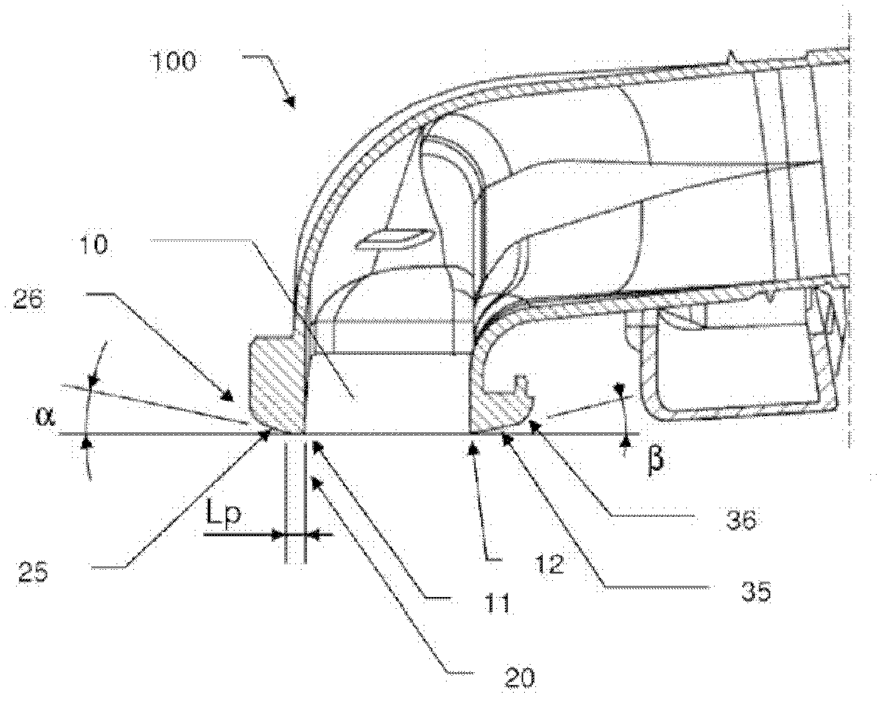
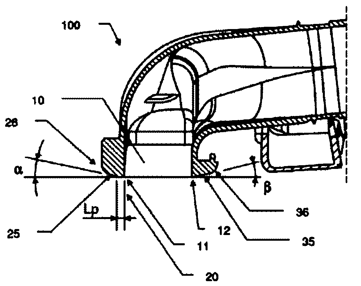
[0016] figure 1 A cutaway view of a vacuum cleaner nozzle base 100 for cleaning textile floors is shown. The base 100 has a suction channel 10 arranged along the entire base 100 . The channel is bounded at the front by a front scraping edge 11 and at the rear by a rear scraping edge 12 . The pressure drop and the air flow rate in the suction channel 10 produced by the suction of the vacuum cleaner motor have values ​​determined in particular according to the resistance loss imposed on the air flow entering into the suction channel 10 . This drag loss depends on the airflow path, which is defined according to the contour of the base 100 . The air flow entering through the front passes under the front scraping edge 11 , but also under the sealing plate 20 . This sealing plate 20 is contained in the wiping plane defined by the two wiping edges 11 and 12 . The width of the sealing panel 20 in contact with the ground requires that the air flow passes over the textile floor at l...


PUM


Abstract

The soleplate (100) has a suction channel (10) that is defined at a front by a front scrapping edge (11) and at a rear by a rear scrapping edge (12). A regulating unit regulates flow-pressure torque of air sucked in the suction channel, where the regulating unit has a sealing cover (20) comprised in a scrapping plane. An advanced effort limiting unit has a front attack chamfer (25) arranged at a front of the sealing cover forming an angle (beta) with the scrapping plane, where the angle is lower than 20 degrees.

Description

technical field [0001] The present invention generally relates to a vacuum cleaner nozzle having a base with improved dust collection efficiency. Background technique [0002] Vacuum cleaner nozzles are known in the prior art for the purpose of providing a dust extraction system whose parameters are controlled. Document GB1458899 presents a vacuum cleaner nozzle whose base has a suction channel delimited at the front and at the rear by flexible sheets. These sheets can be deformed under the effect of the vertical bearing force on the base generated by the reduced pressure in the channel. When deformed, these lamellae modify the effective surface of the channel and adjust the bearing force to allow scraping of the textile floor with a constant force. Scratching refers to the mechanical action of the base on the fur of the textile floor that is to be cleaned. [0003] The systems described above have the disadvantage, in particular, that they do not work efficiently enough....

Claims


Application Information

Patent Timeline
Patent Type & Authority Applications(China)
IPC IPC(8): A47L9/02
CPCA47L9/02
Inventor 赛里·吉诺
Owner SEB SA
Why Eureka
Try Eureka