Vacuum-type rotary slide pump

A technology of rotary vane vacuum pump and sliding vane, which is applied in the direction of rotary piston pump, rotary piston machine, pump, etc., can solve the problems of cost and avoid damage

Active Publication Date: 2014-12-10
LEYBOLD HERAEUS GMBH & CO KG
View PDF7 Cites 2 Cited by
  • Summary
  • Abstract
  • Description
  • Claims
  • Application Information

AI Technical Summary

Problems solved by technology

This is relatively complex, since a valve system to be controlled separa

Method used


Image

  • Vacuum-type rotary slide pump
  • Vacuum-type rotary slide pump
  • Vacuum-type rotary slide pump

Examples


Embodiment Construction

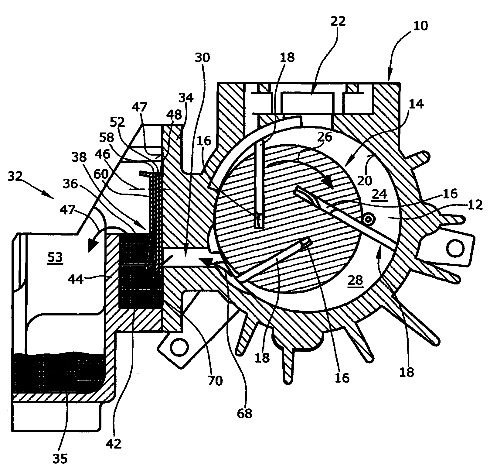
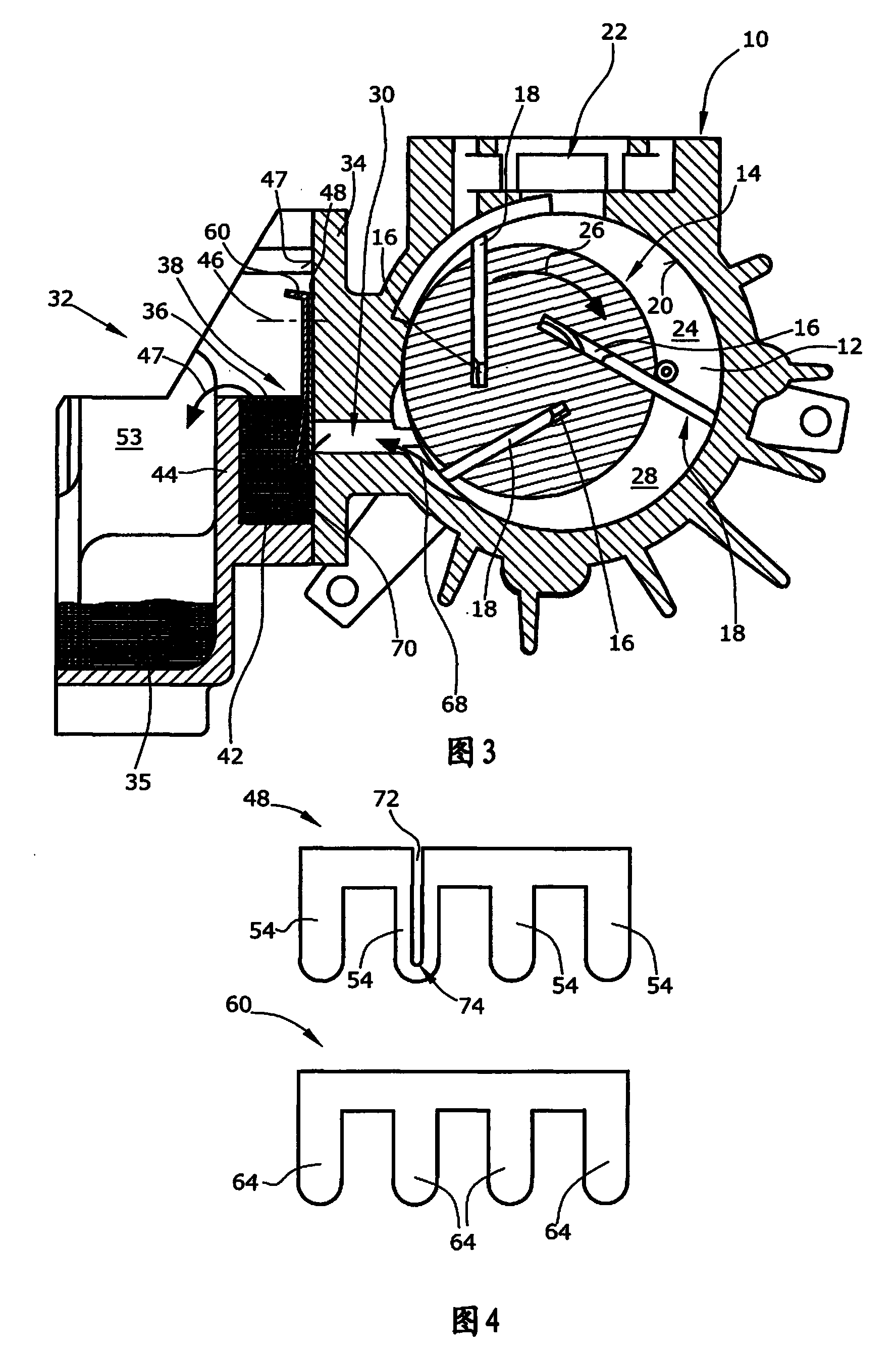
[0028] Rotary vane vacuum pump ( figure 1 ) has a housing 10. Inside the housing 10 there is a rotor 14 in the suction chamber 12 . In the exemplary embodiment shown, the rotor 14 has three vane gaps 16 , in which vane gaps 18 are respectively arranged. The slide 18 is pressed against the inner wall 20 of the suction chamber due to the centrifugal force by the rotation of the rotor 14 .

[0029] The medium is sucked from the chamber to be evacuated into a first region 24 of the suction chamber 12 via a suction opening 22 connected to the chamber to be evacuated. The area 24 of the suction chamber 12 is delimited by two adjacent slides 18 . A region 28 of the suction chamber 12 that is located upstream of the region 24 in the direction of rotation 26 is reduced by the rotation of the rotor 14 , so that the medium located therein is compressed. The medium is conveyed from the area 28 through the outlet channel 30 from the suction chamber 12 in the direction of the oil chamber ...


PUM


Abstract

A vacuum-type rotary slide pump has a pump chamber (12) in a housing (10). A rotor (14) is eccentrically mounted in the pump chamber (12). Slides (18) are connected in a displaceable manner to the rotor (14). Furthermore, a discharge duct (30) is connected to the pump chamber (12) and to an oil chamber (32). Between the discharge duct (30) and the oil chamber (32) there is arranged a valve device (38) for preventing a return flow of medium from the oil chamber (32) into the pump chamber (12). According to invention, at least one compensation duct (50, 72) is provided which is connected to the discharge duct (30) and to the oil chamber (32) and which is integrated into the valve device (38).

Description

technical field [0001] The invention relates to a rotary vane vacuum pump. Background technique [0002] A rotary vane vacuum pump has a suction chamber arranged in a housing. The rotor is arranged eccentrically within the housing. Typically, two or more slides are connected to the rotor in a slide gap. The slide vanes are pressed against the inner wall of the suction chamber by centrifugal force during the rotation of the rotor. To generate the vacuum, the suction opening of the rotary vane vacuum pump is connected to the chamber to be evacuated. Due to the eccentricity of the rotor and the changing size of the chambers formed between the slides, the medium is conveyed through one or more discharge channels. For lubrication and in order to ensure a good seal of the slide plate at the inner wall of the suction chamber, there is always a certain amount of oil present to form an oil film in the suction chamber. Since the discharged medium thus mixes with the oil, at least...

Claims


Application Information

Patent Timeline
IPC IPC(8): F04C29/12F04C29/02F04C18/344
CPCF04C28/28F04C29/128F04C29/026F04C18/3441F04C25/02
Inventor 劳伦特·富雷尔让-弗朗索瓦·奥贝尔弗雷德里克·耶焦罗夫斯基劳伦特·布雷吉耶埃里克·菲戈尼
Owner LEYBOLD HERAEUS GMBH & CO KG
Why Eureka
Try Eureka