Device for preventing hydro-pneumatic spring from swinging

A technology of oil-pneumatic spring and swing device, which is applied in the direction of elastic suspension, transportation and packaging, suspension, etc., can solve the problems of joint bearing damage, noise, etc., and achieve the effect of eliminating noise and reducing swing

Inactive Publication Date: 2012-04-18
CHINA NORTH VEHICLE RES INST
View PDF5 Cites 2 Cited by
  • Summary
  • Abstract
  • Description
  • Claims
  • Application Information

AI Technical Summary

Problems solved by technology

[0002] After the current vehicle oil-gas spring is installed, because the centerlines of the upper and lower mounting rings (mounting holes) are not parallel, the oil-gas spring cylinder and the piston reciprocate while the oil-gas spring cylinder and piston are reciprocating during the suspension movement, causing the oil-gas The spring oil cylinder and the piston reciprocate in the radial direction, causing the joint bearing in the installation hole of the oil and gas spring to be damaged in advance and generate noise

Method used


Image

  • Device for preventing hydro-pneumatic spring from swinging
  • Device for preventing hydro-pneumatic spring from swinging
  • Device for preventing hydro-pneumatic spring from swinging

Examples


Embodiment 1

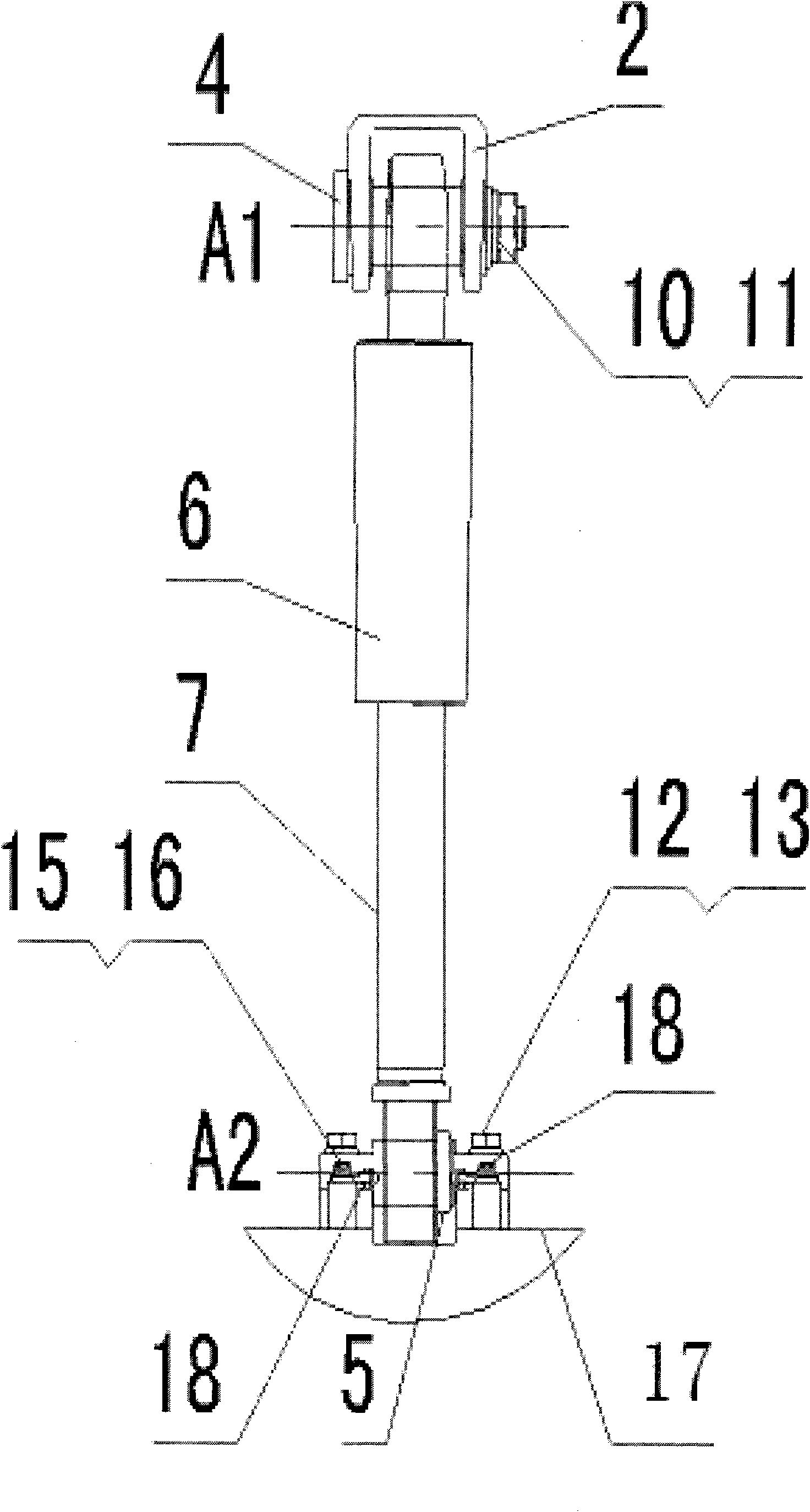
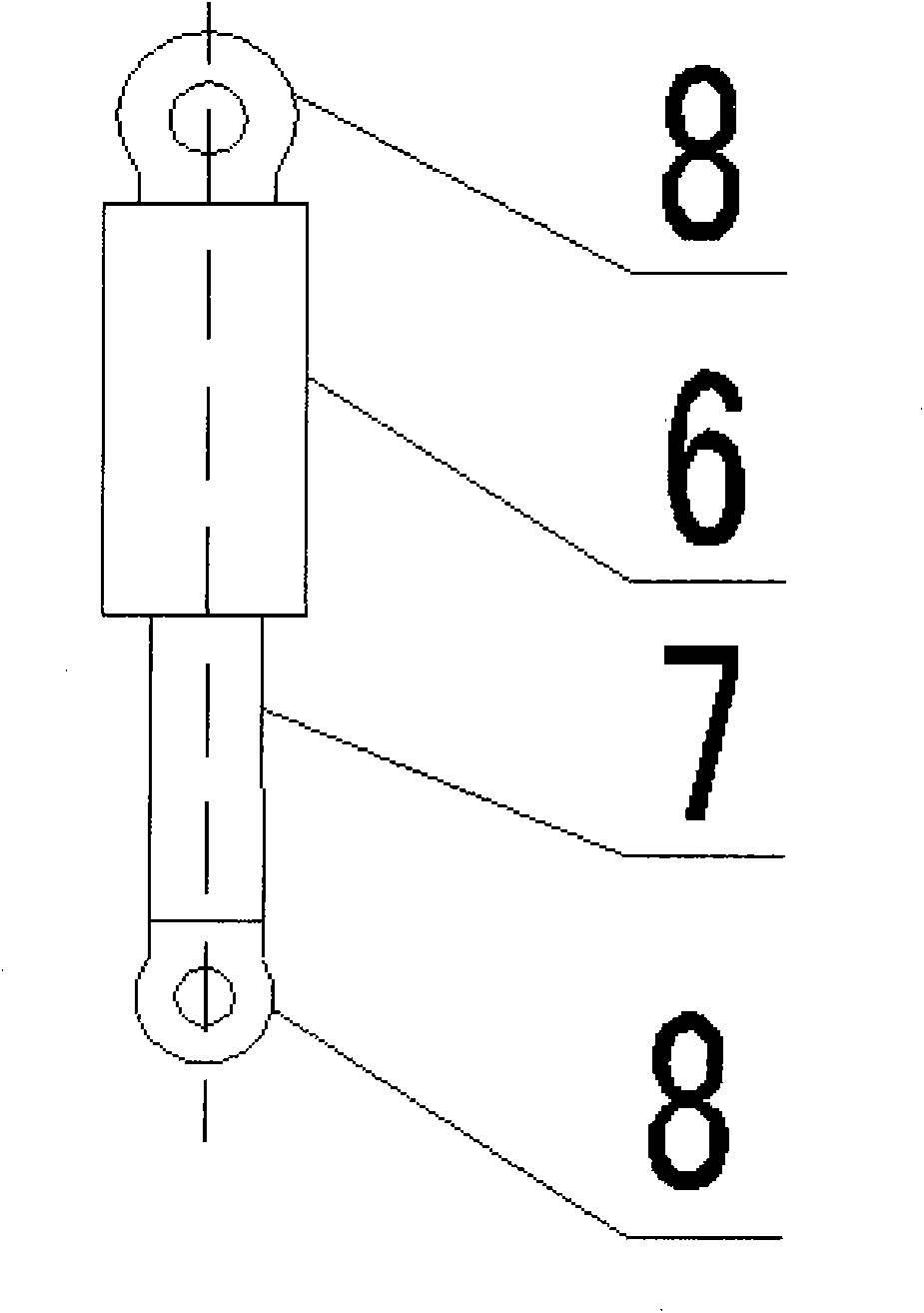
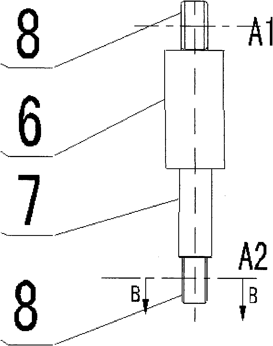
[0032] Such as Figure 1-11 As shown, a device for preventing the oil-pneumatic spring from swinging according to the present example includes an oil-pneumatic spring 3, a cross arm and a mount Q1 on the cross arm. Between the cross arm and the car body 24, to support the weight of the car body 24 and play a damping effect, the upper cross arm, the lower cross arm, the oil-pneumatic spring 3, the wheel hub assembly 14 and the car body 24 constitute a four-bar mechanism. The wheel 9 provides guidance and supports the car body 24; the cross arm includes an upper cross arm 19 and a lower cross arm 17, and the lower cross arm 17 is provided with a mounting seat Q1; there are mounting rings 8 at both ends of the oil and gas spring 3, and the oil and gas The mounting ring 8 at one end of the spring 3 is hinged on the lower cross arm 17 through the lower mounting pin shaft 5, which is actually hinged on the mounting seat Q1, and the lower mounting pin shaft 5 is fixed on the lower cr...

Embodiment 2

[0041] Such as Figure 1-11 As shown, a kind of anti-oil-pneumatic spring swinging device of the present invention, its structure is basically the same as that of Embodiment 1, the difference is:

[0042] In this example, the upper attached seat 2 is provided with an anti-swing ejector mounting seat Q2, and the anti-swing ejector rod installation seat Q2 is provided with an anti-swing ejector rod 18. The centerlines of 8 are parallel, the axes of the anti-sway push rods 18 on both sides of the installation ring 8 are coincident, and the apexes of the anti-sway push rods 18 on both sides are abutted on the end face of the installation ring 8. The distance equals the height of the mounting ring 8.


PUM


Abstract

The invention relates to a fixing device, in particular to a device for preventing a hydro-pneumatic spring from swinging, comprising the hydro-pneumatic spring, a cross arm and a mounting seat arranged on the cross arm, wherein the cross arm is arranged between a vehicle body and a hub assembly; the hydro-pneumatic spring is arranged between the cross arm and the vehicle body; the cross arm consists of an upper cross arm and a lower cross arm, and the lower cross arm is provided with the mounting seat; two ends of the hydro-pneumatic spring are provided with mounting rings, the mounting ring at one end of the hydro-pneumatic spring is hinged to the mounting seat of the lower cross arm, and the mounting ring at the other end of the hydro-pneumatic spring is hinged to the vehicle body; two sides of the mounting seat of the lower cross arm are provided with anti-swing ejector rods, the peaks of the anti-swing ejector rods at the two sides of the mounting seat support against the end surfaces of the mounting rings, and the distance between the two peaks of the anti-swing ejector rods at the two sides of the mounting seat is equal to the height of the mounting rings. In the invention, the two sides of the mounting rings of the hydro-pneumatic spring are provided with the anti-swing ejector rods, therefore, the swing of central lines of the mounting rings at two ends of the hydro-pneumatic spring due to mounting positions and suspension motion can be reduced, and noise caused by the swing can be reduced or eliminated.

Description

Technical field: [0001] The invention relates to a fixing device, in particular to a device for preventing oil and gas springs from swinging. Background technique: [0002] After the current vehicle oil-gas spring is installed, because the centerlines of the upper and lower mounting rings (mounting holes) are not parallel, the oil-gas spring cylinder and the piston reciprocate while the oil-gas spring cylinder and piston are reciprocating during the suspension movement, causing the oil-gas The spring cylinder and the piston reciprocate radially, causing the joint bearing in the oil-gas spring installation hole to be damaged in advance and generate noise. [0003] Therefore, the present invention is proposed aiming at the above-mentioned deficiencies existing in the prior art. Invention content: [0004] The object of the present invention is to provide a device for preventing the oil-gas spring from swinging. Since the two sides of the oil-gas spring installation ring are...

Claims


Application Information

Patent Timeline
Patent Type & Authority Applications(China)
IPC IPC(8): B60G11/26
Inventor 马国新郭晓燕施睿王东亮阴运宝
Owner CHINA NORTH VEHICLE RES INST
Why Eureka
Try Eureka