
Assembled variable-dimension sample box suite

A sample box and size-changing technology, which is applied in the direction of measuring devices, instruments, scientific instruments, etc., can solve the problem that the size of the sample cannot be changed, and achieve the effect of light weight and portability

Active Publication Date: 2012-04-18
SICHUAN UNIV
View PDF6 Cites 14 Cited by
  • Summary
  • Abstract
  • Description
  • Claims
  • Application Information

AI Technical Summary

Problems solved by technology

These tests are performed on the sample under a fixed sample size, and the change in the sample size cannot be realized.

Method used


Image

  • Assembled variable-dimension sample box suite
  • Assembled variable-dimension sample box suite
  • Assembled variable-dimension sample box suite

Examples


Embodiment 1

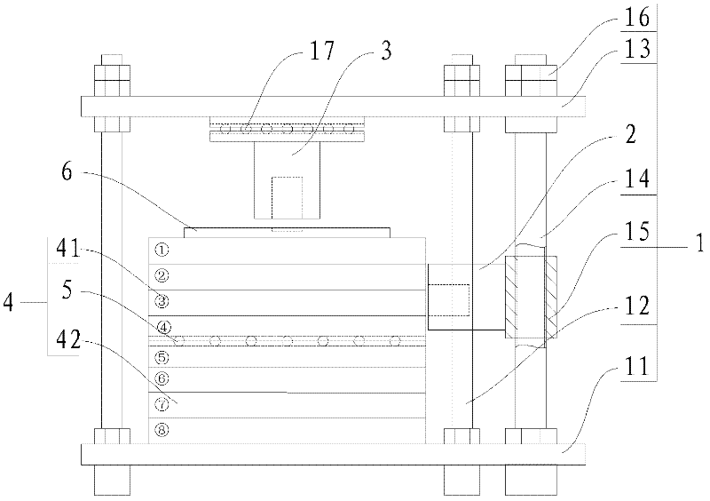
[0054] Such as Figure 1 to Figure 15 As shown, the assembled variable size direct shear compression instrument using the assembled variable size sample box kit of the present invention includes the standard size of the laboratory direct shear test. After the shear plane is artificially set, the test can be Apply several levels of vertical load to the sample for shear or compression test.

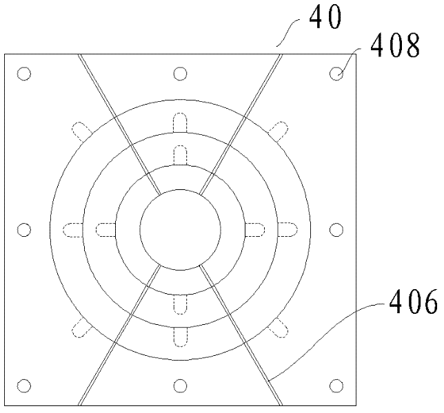
[0055] First, use a steel plate with a thickness of 2.5 cm to make eight sets of sample box rigid assemblies 40 numbered ① to ⑧, that is, the thickness of the sample box rigid assembly 40 used to form the upper shear box 41 or the lower shear box 42 is 2.5 cm. cm, each set of sample box rigid assembly 40 is composed of four concentric steel rings, the outer edge of the outermost steel ring is a square, with a side length of 27 cm, and the center of the center is taken out as a cylinder with a diameter of 20 cm. Thereby forming a hollow ring 1, the hollow ring 1 is provided with bolt holes ...

Embodiment 2

[0074] Such as Figure 2 to Figure 16 As shown, the assembled variable-size double-sided shear instrument using the assembled variable-size sample box kit of the present invention includes the standard size of the laboratory direct shear test, and can apply several levels of vertical load to the sample for double-sided shearing. Shear shear test.

[0075] The assembled variable-size double-sided shearing instrument is based on the assembled variable-size direct shear compression instrument in Embodiment 1, and an assembled variable-size sample box kit is added for the middle shear layer 43 . This set of assembled variable size sample box kits includes 4 sets of sample box rigid components 40 with a height of 2cm. The numbers of these 4 sets of sample box rigid components 40 are respectively ⑨⑩ The basic shape and size of the sample loading rings included in the four sets of sample box rigid assemblies 40 are the same as the sample box rigid assemblies 40 for forming the uppe...


PUM

PropertyMeasurementUnit
Particle sizeaaaaaaaaaa

Abstract

The invention discloses an assembled variable-dimension sample box suite capable of being used for direct shearing and compression test of geotechnical samples in various dimensions. The assembled variable-dimension sample box suite is composed of at least two sets of sample box rigid components which can be interconnected in a manner of stacking up, wherein each set of sample box rigid component is composed of a plurality of mutually nested sample holding rings; in each two adjacent sample holding rings, an external edge of the internal sample holding ring is jointed with an internal edge of the external sample holding ring, and the internal sample holding ring is axially limited in one way by the external sample holding ring; the outermost sample holding ring in one set of sample box rigid component is provided with a sliding support matched structure, moreover, each sample holding ring of the other set of sample box rigid component is provided with a drainage channel, so that the soil body test can have drainage or have no drainage; in the test, variation of dimension of the sample is realized by increasing or reducing the number of layers of the sample box rigid components and the number of the sample holding rings of the sample box rigid components, the assembled variable-dimension sample box suite is convenient to assemble and detach, and also can be used as a setting out device for various geotechnical test instruments.

Description

technical field [0001] The invention relates to a lofting device used in direct shear and compression tests of indoor and outdoor rock and soil bodies. Background technique [0002] In the field of geotechnical engineering, it is often an essential way to obtain the mechanical parameters of rock and soil in the target engineering area through experiments. At present, the mechanical indexes of rock and soil are obtained mainly through laboratory tests. Indoor tests include large and small triaxial tests, direct shear tests, compression tests, etc. Indoor tests included standard ring knife samples and large-sized square box samples. These tests are performed on the sample under a fixed sample size, and changes in the sample size cannot be realized. [0003] In order to study the size effect of the mechanical properties of the same rock and soil sample, to integrate the shear and compression tests of samples of different sizes and shapes, and to carry out tests in the field,...

Claims


Application Information

Patent Timeline
IPC IPC(8): G01N3/02
Inventor 符文熹郑星
Owner SICHUAN UNIV
Learn More