Automatic terminal riveting mechanism

A technology of riveting mechanism and terminal crimping, which is applied in the direction of connection, electrical components, circuits, etc., can solve the problems of complex structure of the main part, inconvenient maintenance, and low work efficiency, so as to improve the precision, safety and maintenance of terminal crimping And the effect of convenient troubleshooting, simple structure and scientific

Active Publication Date: 2012-04-18
山东隽宇电子科技有限公司
View PDF7 Cites 13 Cited by
  • Summary
  • Abstract
  • Description
  • Claims
  • Application Information

AI Technical Summary

Problems solved by technology

[0002] With the development of the electronics industry, in order to improve production efficiency, the division of labor in manufacturing is becoming more and more detailed. At present, there is an industry specializing in terminal crimping, while traditional terminal crimping needs to be done manually from wire feeding to terminal crimping. The efficiency is low, and the error is large. Although there are some machines that specialize in crimping terminals, they can only realize the function of terminal crimping, and the transportation of terminals still needs to rely on manual or additional terminal conveying equipment. The difference in coordination leads to low accuracy of delivery and increases the cost; and the traditional terminal crimping machine uses a drive system to control the upper die to press the lower die to achieve terminal crimping. In this way, the main body of the terminal crimping machine The parts are all arranged at the upper end, which makes the structure of the main part complicated and inconvenient to maintain, and its center of gravity is concentrated on the upper end, which easily causes the center of gravity to be unstable, making the crimping accuracy not high, and easily causing accidents

Method used


Image

  • Automatic terminal riveting mechanism
  • Automatic terminal riveting mechanism
  • Automatic terminal riveting mechanism

Examples


Embodiment Construction

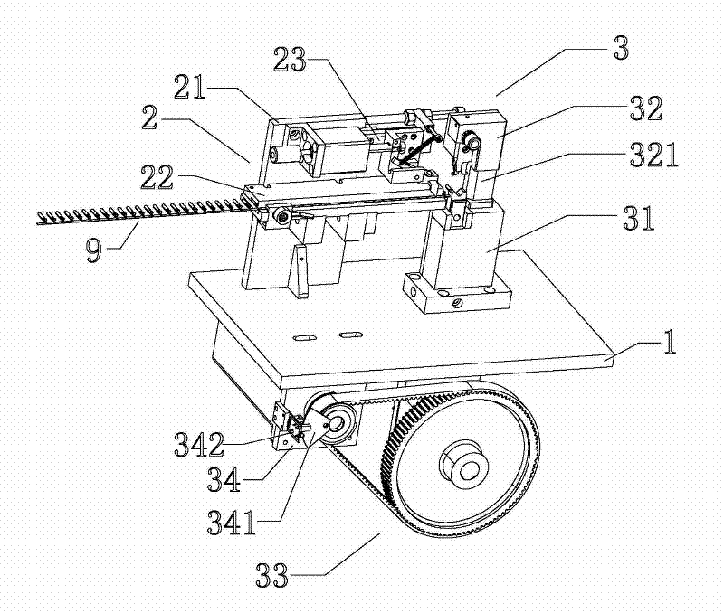
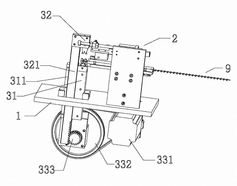
[0022] refer to Figure 1 to Figure 5 , Figure 1 to Figure 5 It is a schematic structural diagram of the present invention. As shown in the figure, an automatic terminal riveting mechanism includes a base 1, a terminal conveying mechanism 2 installed on the base 1, and a terminal crimping mechanism 3. The terminal crimping mechanism 3 is installed on On the base 1, and located in the terminal output direction of the terminal delivery mechanism 2, the terminal crimping mechanism 3 includes a lower mold assembly 31 fixed on the base 1, an upper mold assembly 32 arranged on the upper side of the lower mold assembly 31, And the die drive assembly 33 arranged on the lower side of the base 1, the die drive assembly 33 includes a motor 331 and an output gear 333 arranged on the base 1, and the motor 331 is connected with the output gear 333 through a speed change device. In this embodiment Among them, the transmission device is a large gear 332 arranged on the base 1 through a conn...


PUM


Abstract

The invention discloses an automatic terminal riveting mechanism, which comprises a pedestal, and a terminal conveying mechanism and a terminal pressing mechanism which are respectively arranged on the pedestal, wherein the terminal pressing mechanism is positioned in the output direction of the terminal conveying mechanism; a pressing die driving assembly is arranged on the lower side of the pedestal; the terminal conveying mechanism can convey terminals to the terminal pressing mechanism according to certain frequency; and the pressing die driving assembly controls the terminal pressing mechanism to press the terminals through a connecting mechanism, and the terminals can be continuously pressed by continuous circulation. Because the terminal conveying mechanism and the terminal pressing mechanism are arranged on the same pedestal and collocated correspondingly, the conveying precision of the terminals is improved; the pressing die driving assembly is arranged on the lower side of the pedestal, so the automatic terminal riveting mechanism is simple and scientific in structure, low in cost and very convenient to maintain and eliminate faults; and because the gravity center of the whole automatic terminal riveting mechanism is on the lower part, the stability, the safety and the terminal pressing precision of the terminal riveting mechanism are improved.

Description

technical field [0001] The invention relates to an automatic terminal riveting mechanism. Background technique [0002] With the development of the electronics industry, in order to improve production efficiency, the division of labor in manufacturing is becoming more and more detailed. At present, there is an industry specializing in terminal crimping, while traditional terminal crimping needs to be done manually from wire feeding to terminal crimping. The efficiency is low, and the error is large. Although there are some machines that specialize in crimping terminals, they can only realize the function of terminal crimping, and the transportation of terminals still needs to rely on manual or additional terminal conveying equipment. The difference in coordination leads to low accuracy of delivery and increases the cost; and the traditional terminal crimping machine uses a drive system to control the upper die to press the lower die to achieve terminal crimping. In this way,...

Claims


Application Information

Patent Timeline
Patent Type & Authority Applications(China)
IPC IPC(8): H01R43/052H01R43/055
Inventor 龚广诗赵维李业
Owner 山东隽宇电子科技有限公司
Why Eureka
Try Eureka