Piezoelectric motor, robot hand, robot, electronic component transporting apparatus, electronic component inspecting apparatus, liquid feeding pump, printing apparatus, electronic timepiece, projecting apparatus, and transporting apparatus

a technology of electronic components and motors, applied in the direction of positive displacement liquid engines, hoisting equipment, machines/engines, etc., can solve the problems of sacrificing stiffness, lowering the driving accuracy of objects, and the type of structure the vibration case needs, so as to achieve high driving accuracy and high transporting accuracy

Inactive Publication Date: 2014-03-20
SEIKO EPSON CORP
View PDF2 Cites 5 Cited by
  • Summary
  • Abstract
  • Description
  • Claims
  • Application Information

AI Technical Summary

Benefits of technology

[0050]In this configuration, since the piezoelectric motor being compact and having a high driving accuracy is mounted, a transporting apparatus being compact and having a high transporting accuracy can be realized.

Problems solved by technology

However, in the piezoelectric motor of a type in which the vibration case having the vibrator integrated therein is accommodated in the outer case, what kind of structure the vibration case needs to have is not known.
In other words, when stiffness of the vibration case is not sufficient, the vibration case may be deflected due to the vibration of the vibrator or a reaction force generated when the object is driven and hence the driving accuracy of the object is lowered, or a sliding movement with respect to the outer case may be interfered and hence the projection of the vibrator cannot be pressed against the object.
In addition, cable routing also needs to be considered for applying the drive voltage on the vibrator, and sacrificing the stiffness of the vibration case for the cable routing is not preferable.
In this manner, a structure of the vibration case significantly affects the size of the piezoelectric motor, the driving accuracy, and the cable routing to the vibrator, and there is a problem that the structure of the vibration case from these points of view is not considered yet.
There may be a case where the routed cable needs to be drawn out obliquely due to layout restrictions and the like when mounting the piezoelectric motor.

Method used


Image

  • Piezoelectric motor, robot hand, robot, electronic component transporting apparatus, electronic component inspecting apparatus, liquid feeding pump, printing apparatus, electronic timepiece, projecting apparatus, and transporting apparatus
  • Piezoelectric motor, robot hand, robot, electronic component transporting apparatus, electronic component inspecting apparatus, liquid feeding pump, printing apparatus, electronic timepiece, projecting apparatus, and transporting apparatus
  • Piezoelectric motor, robot hand, robot, electronic component transporting apparatus, electronic component inspecting apparatus, liquid feeding pump, printing apparatus, electronic timepiece, projecting apparatus, and transporting apparatus

Examples


first embodiment

A. Configuration of Apparatus

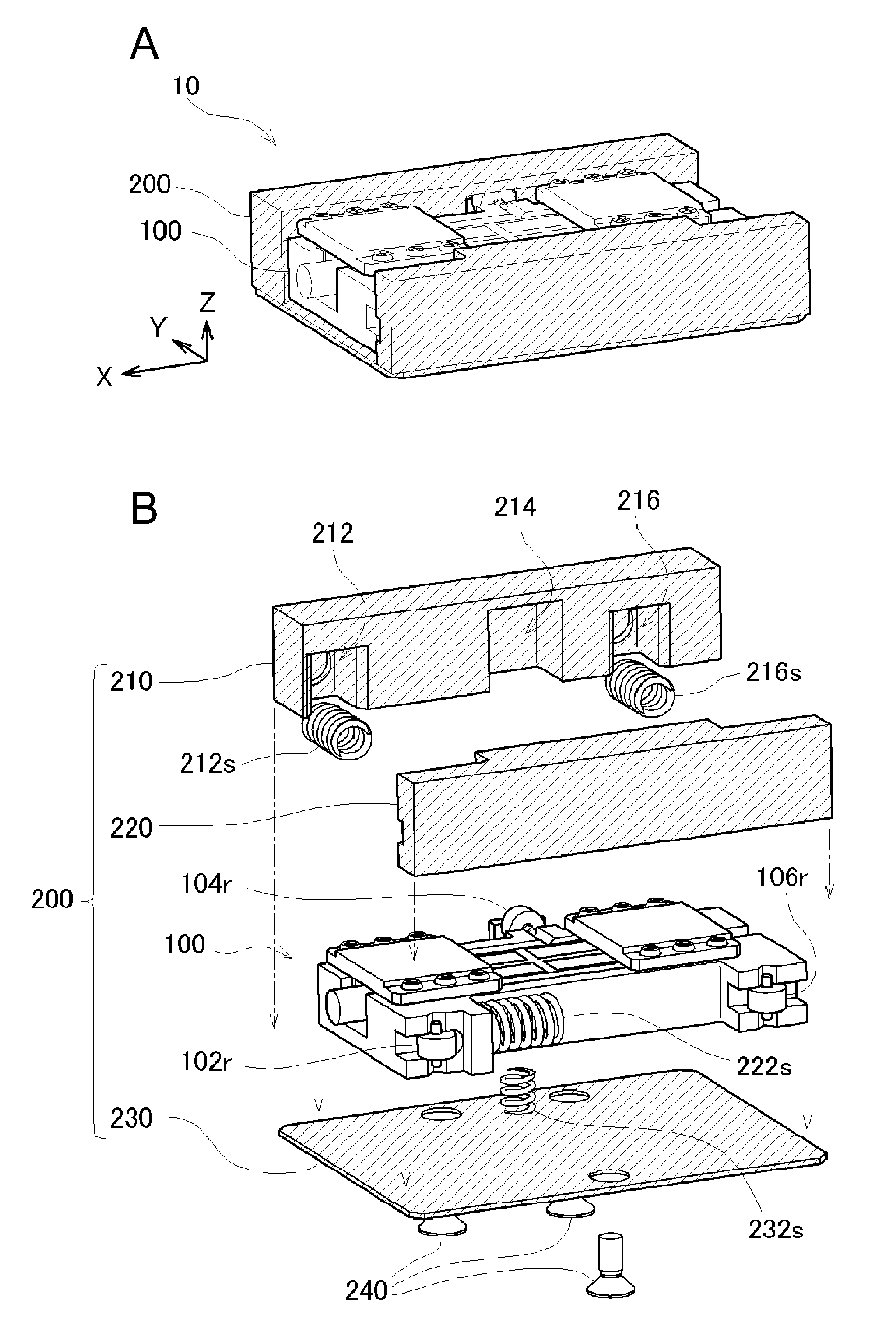
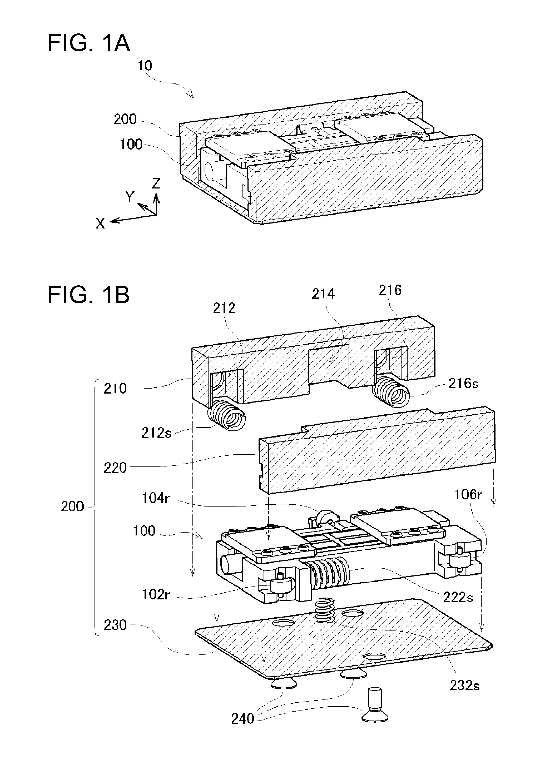
[0078]FIGS. 1A and 1B are explanatory drawings illustrating a rough configuration of a piezoelectric motor 10 of a first embodiment. FIG. 1A illustrates a general view of the piezoelectric motor 10 of the first embodiment, and FIG. 1B illustrates an exploded view. As illustrated in FIG. 1A, the piezoelectric motor 10 of the first embodiment roughly includes a body portion 100 and an outer case 200. The body portion 100 is mounted inside the outer case 200, and in this state, is movable in one direction. In this specification, the direction of movement of the body portion 100 is referred to as “X direction”. As illustrated in the drawings, directions orthogonal to the X direction are referred to as “Y direction” and “Z direction”, respectively.

[0079]The body portion 100 and the outer case 200 are each composed of a plurality of components combined each other. For example, the outer case 200 is composed of a first side wall block 210 and a second side wall...

first modification

D-1. First Modification

[0101]In the first embodiment described above, the vibrator 112 is held via the shock-absorbing members 130. However, the holding configuration is not limited thereto. For example, as conceptually illustrated in FIG. 6A, the vibrator 112 may be supported by projections 122d projecting from a coupling portion 122c of a vibration case 122.

[0102]FIG. 6B illustrates a cross-sectional view of the vibration case 122 of a first modification taken along an YZ plane. In the drawing, the vibrator 112 assembled into the vibration case 122, the shock-absorbing member 130, and the holding lid 144 are also illustrated by broken lines. As illustrated, according to the first modification, the projection 122d projecting from the vibration case 122 is in contact with the vibrator 112.

[0103]As publicly known, when an AC voltage is applied to the vibrator 112 for vibration, the vibrator 112 generates heat. Consequently, if the temperature of the vibrator 112 is extraordinarily in...

second modification

D-2. Second Modification

[0106]In the first embodiment described above, as illustrated in FIG. 4A, the coupling portion 120c of the vibration case 120 has been described as being formed to have a flat surface on the side facing the vibrator 112. Then, in the description, the shock-absorbing members 130, the vibrator 112, and the shock-absorbing members 130 are stacked on this flat surface in this order to hold the vibrator 112 (see FIG. 2). However, the vibrator 112 may be held by providing depressions in the coupling portion 120c of the vibration case 120 and stacking the vibrator 112 and the shock-absorbing members 130 in this order on the shock-absorbing members 130 provided in this depression.

[0107]FIG. 7A conceptually illustrates a vibration case 124 of a second modification configured as described above. As illustrated, depressions 124d are formed in a coupling portion 124c of the vibration case 124 at two positions corresponding to the nodes of the bending vibration of the vib...


PUM


Abstract

A vibration case includes a first side portion and a second side portion provided on the both sides of a vibrator in a bending direction and a coupling portion configured to couple the first side portion and the second side portion. In this configuration, stiffness of the vibrator in the bending direction is increased, and the deformation of the vibration case may be suppressed. This structure contributes to reduction in size of the vibration case as long as the same stiffness is secured, and hence the size of the vibration case may be reduced while securing high stiffness. Therefore, a piezoelectric motor having a driving accuracy secured sufficiently may be realized while suppressing increase in size of the piezoelectric motor.

Description

BACKGROUND[0001]1. Technical Field[0002]The present invention relates to a piezoelectric motor, a robot hand, a robot, an electronic component carrier apparatus, an electronic component inspecting apparatus, a liquid feeding pump, a printing apparatus, an electronic timepiece, a projecting apparatus, and a carrier apparatus.[0003]2. Related Art[0004]A piezoelectric motor of a system which generates a stretching vibration and a bending vibration simultaneously by applying a drive voltage on a vibrator formed so as to include a piezoelectric material and friction-drives an object by a projection formed on an end surface of the vibrator is known (JP-A-2008-187768). The piezoelectric motor drives the object by vibrating the vibrator at small amplitude and a high frequency, and hence has advantages that the object may be positioned at a high resolution performance and, in addition, the object may be driven rapidly.[0005]Since the piezoelectric motor of this system drives the object with ...

Claims


Application Information

Patent Timeline
Patent Type & Authority Applications(United States)
IPC IPC(8): H02N2/04F04B43/09B25J18/02B41J19/20B25J15/08
CPCH02N2/04B41J19/202F04B43/095B25J18/02B25J15/08B25J9/12B25J15/0253H02N2/004H02N2/005H02N2/026H02N2/028H02N2/103Y10T74/20317B25J18/04F04B43/04
Inventor NISHIMURA, YOSHITERU
Owner SEIKO EPSON CORP
Why Eureka
Try Eureka