Gas generator

一种气体发生器、气体通道的技术,应用在气体发生装置、化学仪器和方法、车辆安全安排等方向,能够解决压力升高、气体流动困难、不能容易地燃烧全部气体发生剂等问题

Active Publication Date: 2012-04-18
DAICEL CHEM IND LTD
View PDF7 Cites 7 Cited by
  • Summary
  • Abstract
  • Description
  • Claims
  • Application Information

AI Technical Summary

Problems solved by technology

[0006] However, when this gas generator is activated, the gas generating agent 16 on the side of the spreading agent 24 burns first, and therefore, the generated gas passes through the unburned gas generating agent 16 to flow to the hole 18, which makes the gas flow difficult.
Therefore, the pressure inside the inner casing 14 rises, and this pressure increase may cause the constituent elements of the gas generator to break down.
Moreover, the entire gas generating agent 16 cannot be easily burned

Method used


Image

  • Gas generator
  • Gas generator
  • Gas generator

Examples


Embodiment approach

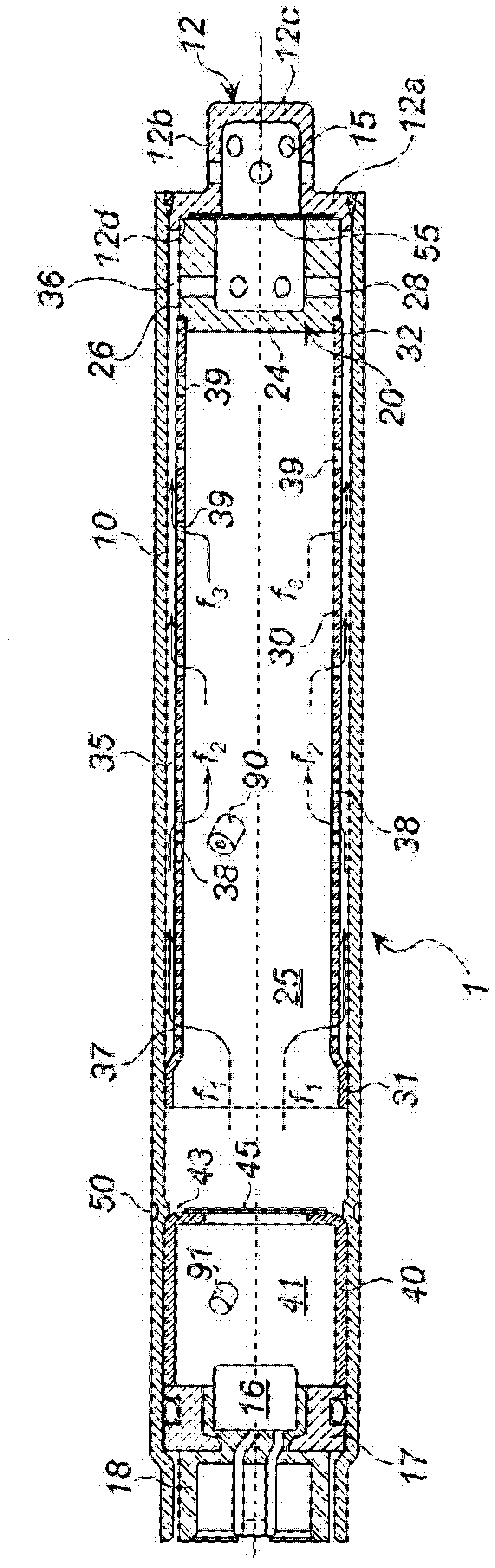
[0043] (1) figure 1 gas generator

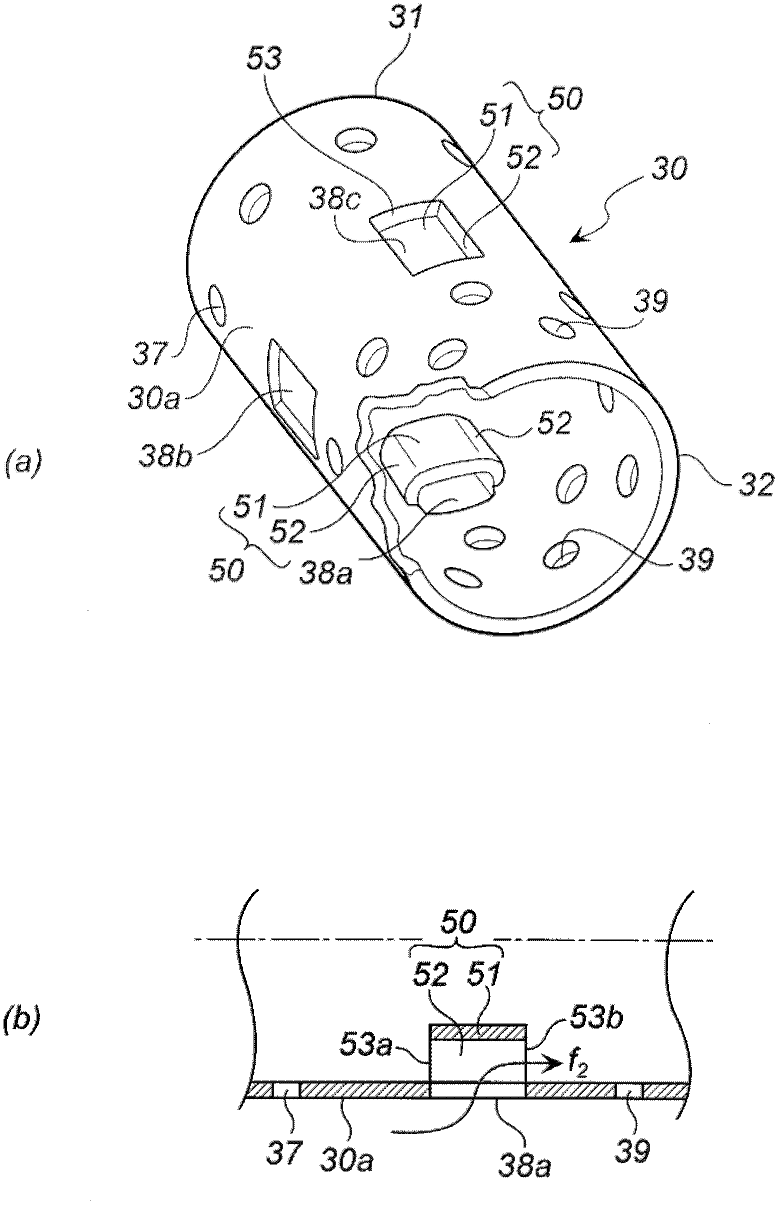
[0044] refer to figure 1 Examples of the present invention will be described. figure 1 is a sectional view of the gas generator 1 along the axial direction. However, it is worth noting that, figure 1 Do not show figure 2 The protruding portion 50 of the tubular element is shown in .

[0045] Ignition means including an igniter 16 and a first gas generating agent 91 are connected to one end of the tubular housing 10 . The first gas generating agent 91 is used as a propagating agent. The igniter 16 is bonded together with a metal igniter collar 17 by resin 18 and fixed to one end of the tubular housing 10 . The ratio (L / D) between the length (L) and the outer diameter (D) of the tubular housing 10 is preferably 4 to 8, but is not limited to this range.

[0046] The first gas generating agent 91 is charged into the booster agent containing chamber 41 formed by the tubular holder 40 . The opening portion at one end of the tubular holde...


PUM


Abstract

Gas generator including: a tubular housing (10), an ignition device (16) attached at one end and a diffuser (12) having a gas discharge port (20), attached at the other end, a tubular member (30), being disposed inside the tubular housing (10) and a tubular gap (36) leading to the gas discharge port is formed, a combustion chamber (25) provided inside the tubular member (30) for accommodating a gas generating agent, a first gas passage hole and a second gas passage hole formed on the first end side and the second end side, respectively, and an opening portion formed between the first gas passage hole and the second gas passage hole, such that they are communicating the combustion chamber (25) with the tubular gap (36), a projecting portion (50) provided in the opening portion such that the projecting portion projects into at least one of the combustion chamber (25) and the tubular gap (36).

Description

field of invention [0001] The present invention relates to a gas generator used in a restraint device installed in a vehicle, such as an air bag system, etc., and more particularly to a gas generator used in a side impact air bag system for disabling the air bag on the passenger side Expand. Background technique [0002] Gas generating devices of side airbags for protecting occupants during side collisions are generally formed in an elongated shape due to limitation of connection positions. [0003] US-A No. 2008 / 0078486 discloses a filterless gas generator, wherein an initiator (initiator) 32 is housed in one end of an elongated housing 12 and a diffuser with gas discharge port 20 is formed. The device portion is disposed in the opposite end. [0004] In the gas generator, a booster cup 23 storing a booster agent and a divider 28 are arranged near the igniter 32 , and an opening 28 a is formed in the divider 28 . The gas generating agent 16 is arranged in the space forme...

Claims


Application Information

Patent Timeline
Patent Type & Authority Applications(China)
IPC IPC(8): B60R21/264B60R21/261B01J7/00B60R21/26
CPCB60R21/2644B60R21/261
Inventor 山崎征幸花野铁平
Owner DAICEL CHEM IND LTD
Why Eureka
Try Eureka