Oil heating system

A technology of oil heating and oil tank, applied in the direction of coating, device for coating liquid on the surface, etc., can solve the problem of temperature control and other problems, and achieve the effect of precise control of hydraulic oil temperature

Inactive Publication Date: 2012-04-25
WUXI JIANGSU WEIFENG PRINTING MACHINE
View PDF6 Cites 2 Cited by
  • Summary
  • Abstract
  • Description
  • Claims
  • Application Information

AI Technical Summary

Problems solved by technology

[0003] The technical problem to be solved by the present invention is to overcome the problem of temperature control of the heating rollers in the existing coating compound equipment, and to provide an oil heating system

Method used


Image

  • Oil heating system
  • Oil heating system

Examples


Embodiment Construction

[0009] The preferred embodiments of the present invention will be described below in conjunction with the accompanying drawings. It should be understood that the preferred embodiments described here are only used to illustrate and explain the present invention, and are not intended to limit the present invention.

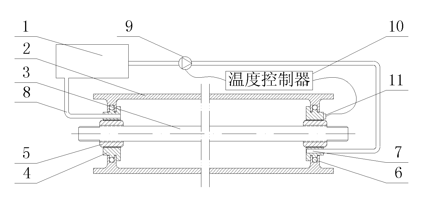
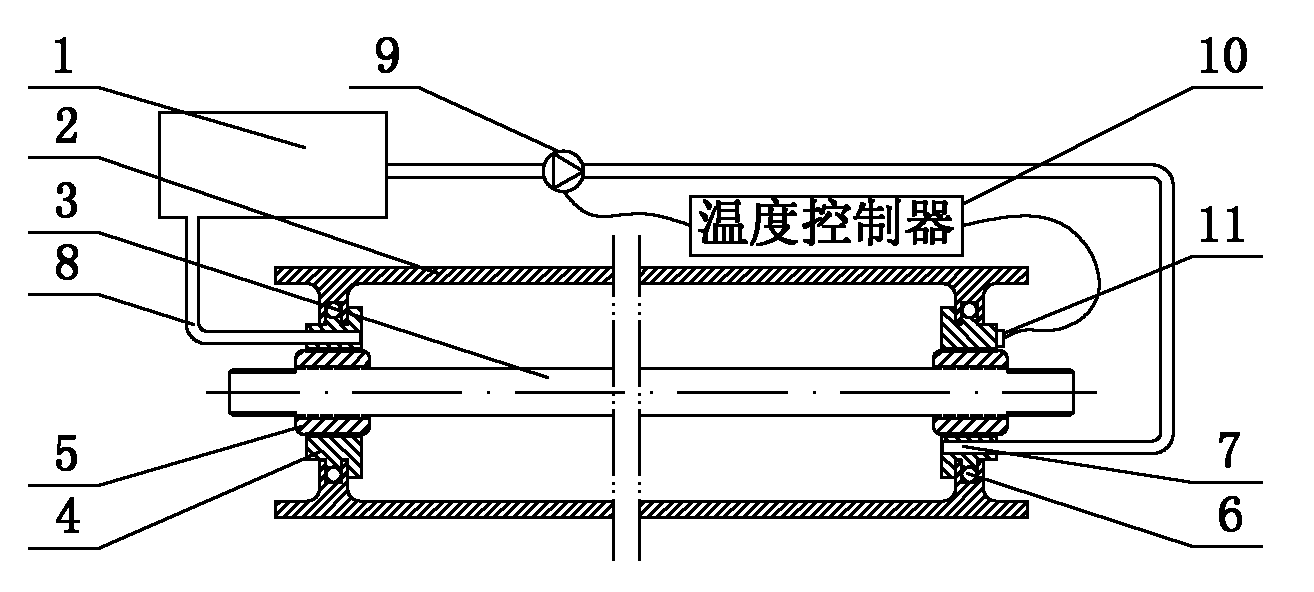
[0010] Such as figure 1 As shown, the oil heating system of the present invention includes an oil tank 1, a roller shell 2, and a drive shaft 3, and the two ends of the roll shell 2 are respectively connected to the sealing block 5 on the drive shaft 3 through a rotary joint 4, The sealing block 5 is fixed on both ends of the drive shaft 5, and the sealing block 5 is locked and sealed with the rotary joint 4, and the rotary joint and the roller shell are connected by a rotary seal, and the roller shell 2 The connecting surface is provided with an inner recessed groove, and a sealing ring 6 is arranged inside the inner recessed groove, and hydraulic oil holes 7 are r...


PUM


Abstract

The invention provides an oil heating system, which comprises an oil tank, a roller casing and a driving shaft. Two ends of the roller casing are respectively connected with sealing blocks on the driving shaft through rotary joints, the sealing blocks are fixed on two ends of the driving shaft, the sealing block and the rotary joint are locked and hermetically connected, hydraulic oil apertures are respectively opened on two rotary joints, a hydraulic oil pipe is connected on each hydraulic oil aperture, two hydraulic oil pipes are respectively connected to the oil inlet and the oil outlet of the oil tank, a hydraulic pump is provided on the hydraulic oil pipe of the oil outlet of the oil tank; the hydraulic pump is connected with a temperature controller. The oil heating system has the beneficial effect that high temperature hydraulic oil in the oil tank can be continuously and circularly delivered in the roller casing by the hydraulic system, the temperature data can be detected through a temperature sensor and then sent to the temperature controller, the rotation speed of the hydraulic pump can be controlled by the temperature controller, so that the oil temperature of the hydraulic oil in the roller casing can be controlled and the effect of accurate control of the hydraulic oil temperature can be reached.

Description

technical field [0001] The invention relates to an oil heating system, which belongs to the network roller heating device for heating and compounding material strips in the field of coating and compounding equipment. Background technique [0002] The most core component in the field of coating compliance equipment is the compound heating roller structure. The temperature of the compound directly determines the quality of the material tape after compounding. If the temperature is too low, the effect of compounding cannot meet the requirements, and it must be reheated and compounded in the later stage, which reduces the work efficiency; at the same time, the speed of compounding and the stability of temperature are also low. It will have a decisive impact on the quality of the product. Now in the equipment of the composite field, it is necessary to coordinate and control the above-mentioned various factors together in order to be able to produce products that meet the quality ...

Claims


Application Information

Patent Timeline
Patent Type & Authority Applications(China)
IPC IPC(8): B05C9/14B05C11/00
Inventor 吴伟平
Owner WUXI JIANGSU WEIFENG PRINTING MACHINE
Why Eureka
Try Eureka