Eureka AIR delivers breakthrough ideas for toughest innovation challenges, trusted by R&D personnel around the world.

Fall-away type screw rolling machine

A thread rolling machine and thread rolling technology, which is applied in the field of thread rolling forming, can solve problems such as cracking or deformation, manual control, and low fullness rate of thread teeth, and achieve the effect of avoiding cracking or deformation

Active Publication Date: 2014-07-30
广州港汉机械有限公司 +1
View PDF3 Cites 0 Cited by
  • Summary
  • Abstract
  • Description
  • Claims
  • Application Information

AI Technical Summary

Problems solved by technology

[0003] The thread rolling method of the existing thread rolling machine is progressive rolling. Whether it is radial rolling or axial rolling during work, the rolling thread is formed by continuously increasing the feed force. This thread rolling When the machine is processing pipe fittings with thinner pipe walls and seamed pipe fittings, the processed pipe fittings are prone to cracking or deformation with the increase of feed force, and the radial force during processing is manually controlled feed. The fullness rate of thread teeth produced by pressing is also low

Method used


Image

  • Fall-away type screw rolling machine
  • Fall-away type screw rolling machine
  • Fall-away type screw rolling machine

Examples


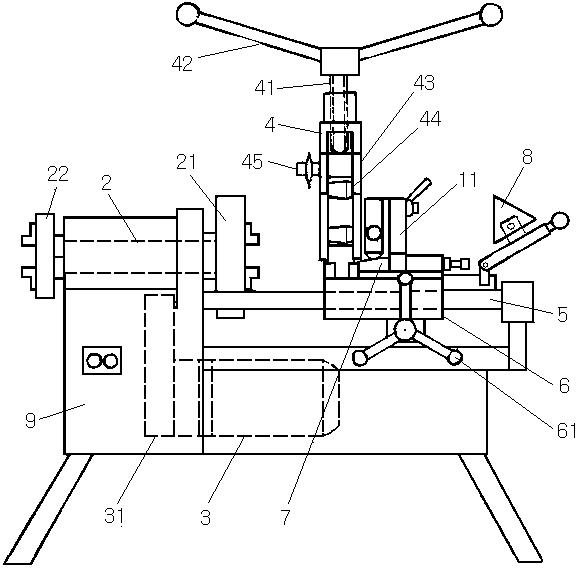
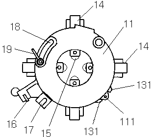
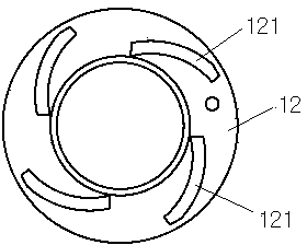
Embodiment Construction

[0027] The embodiments of the present invention will be described in further detail below in conjunction with the accompanying drawings, but the present embodiments are not intended to limit the present invention, and any similar structures and similar changes of the present invention should be included in the protection scope of the present invention.

[0028] Such as Figure 1-Figure 4 As shown, a progressively retreating thread rolling machine provided by the first embodiment of the present invention includes a machine base 9, a thread rolling wheel 11, a main shaft 2, and a sizing blanking frame 4;

[0029] Described machine base 9 is provided with the supporting foot of landing, and its upper end is fixed with horizontal left and right to linear guide rail 5, and described linear guide rail 5 is provided with a carriage 6 that slides along its track line, and described machine base 9 is provided with for A carriage handle 61 that controls the sliding of the carriage 6;

...


PUM


Abstract

The invention provides a fall-away type screw rolling machine, relating to the technical field of rolling forming of screw threads and aiming to avoid cracking pipe fittings and increase the full ratio of screw-thread teeth. The screw rolling machine comprises an engine base, a screw rolling wheel disc and a main shaft, wherein a straight-line guide rail is fixedly arranged at the upper end of the engine base and a slide frame is arranged on the straight-line guide rail; the screw rolling wheel disc is installed on the slide frame, the main shaft is installed at the upper end of the engine base and clamping discs are arranged at two ends of the main shaft; the slide frame is provided with an inclined block and the upper end face of the inclined block is an inclined plane; the screw rolling wheel disc is provided with a curve disc and a small front disc; the curve disc is provided with at least three centrifugal arc-shaped wheel framework limiting strips; the small front disc is provided with at least three wheel frameworks which slide along the radial direction and a pulley which tightly supports against the upper end surface of the inclined block is arranged at the outer edge of the small front disc; each wheel framework is provided with a wheel framework limiting groove which is matched with each framework limiting strip; and a screw rolling wheel is arranged at the inner end of each wheel framework. The screw rolling machine provided by the invention is particularly suitable for rolling pipe screw threads on seamed or seamless thin-wall pipe fittings.

Description

technical field [0001] The invention relates to thread rolling forming technology, in particular to the technology of a progressive retreat thread rolling machine. Background technique [0002] The thread rolling machine is a multifunctional cold rolling forming machine tool, which is used to process threads on workpieces in a cold state. [0003] The thread rolling method of the existing thread rolling machine is progressive rolling. Whether it is radial rolling or axial rolling during work, the rolling thread is formed by continuously increasing the feed force. This thread rolling When the machine is processing pipe fittings with thinner pipe walls and seamed pipe fittings, the processed pipe fittings are prone to cracking or deformation with the increase of feed force, and the radial force during processing is manually controlled feed. The fullness rate of thread teeth produced by pressing is also low. Contents of the invention [0004] In view of the above-mentioned ...

Claims


Application Information

Patent Timeline
Patent Type & Authority Patents(China)
IPC IPC(8): B21H3/02
Inventor 肖金安
Owner 广州港汉机械有限公司
Why Eureka
Eureka Blog
Learn More