High-speed cap closing machine

A high-speed, cap-arranging machine technology, applied in metal processing, metal processing equipment, manufacturing tools, etc., can solve the problems of limited bottle cap production efficiency improvement space, time consumption, high cost, saving production cycle and maximizing production efficiency , the effect of noise reduction

Active Publication Date: 2012-04-25
GUANGZHOU RIJING AUTOMATION MACHINERY CO LTD
View PDF6 Cites 6 Cited by
  • Summary
  • Abstract
  • Description
  • Claims
  • Application Information

AI Technical Summary

Problems solved by technology

[0003] Most of the existing capping machines use the method of pressing first and then spinning to produce bottle caps. Because the pressing and rotating device and the feeding mechanism are in relative motion, when feeding, the pressing and rotating device is in a static state, while When the pressing and spinning device is moving, the feeding mechanism must be still, and the feeding, pressing and screwing will take double time. However, considering the stability of the whole machine, the feeding, pressing and spinning time cannot be reduced to too small. The existing capping machine has the disadvantages of high cost, low efficiency, and long time consumption, which seriously limits the room for improving the production efficiency of bottle caps.

Method used


Image

  • High-speed cap closing machine
  • High-speed cap closing machine
  • High-speed cap closing machine

Examples


Embodiment Construction

[0031] In order to make the object, technical solution and advantages of the present invention clearer, the present invention will be further described in detail below in conjunction with the accompanying drawings and embodiments.

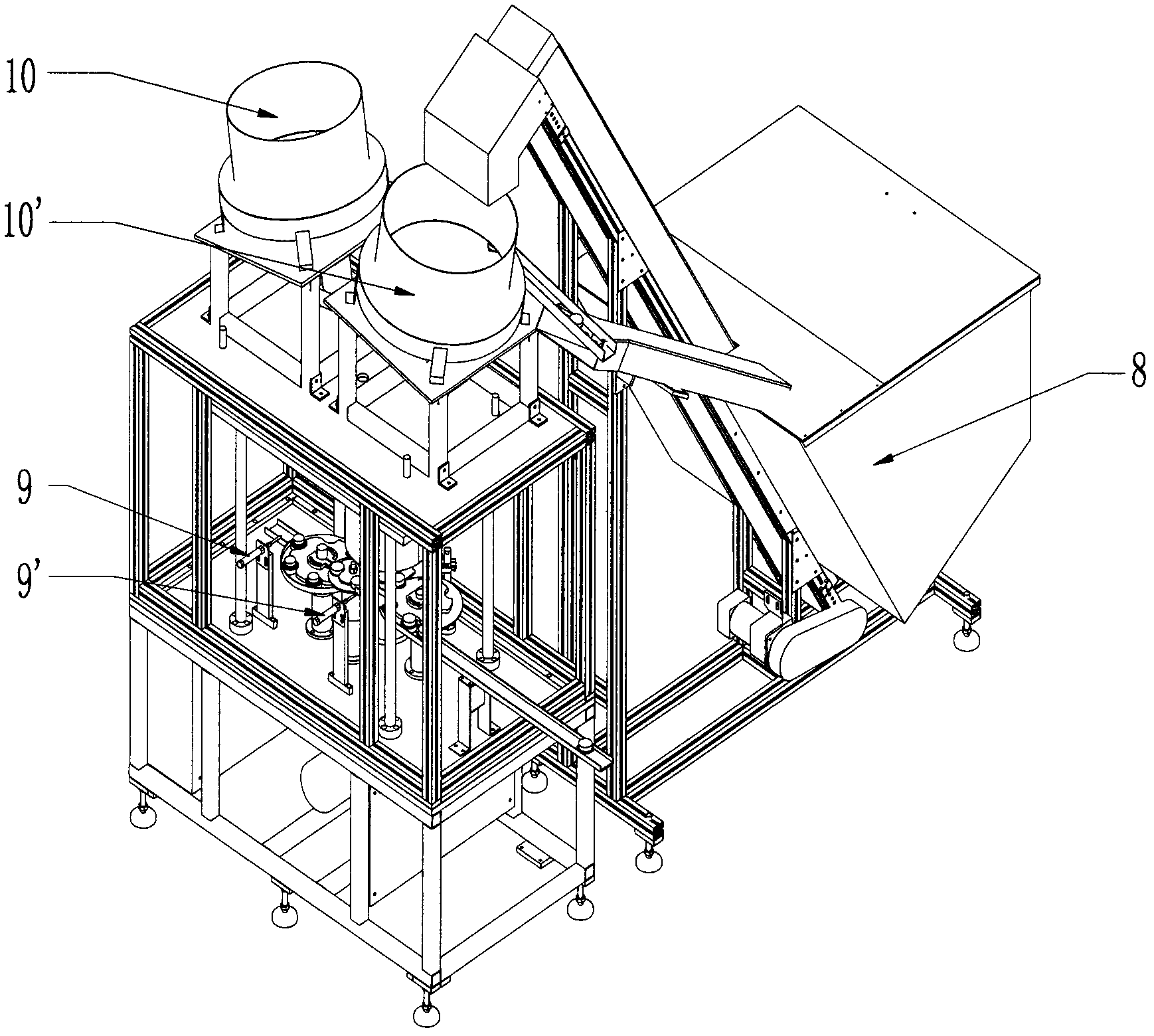
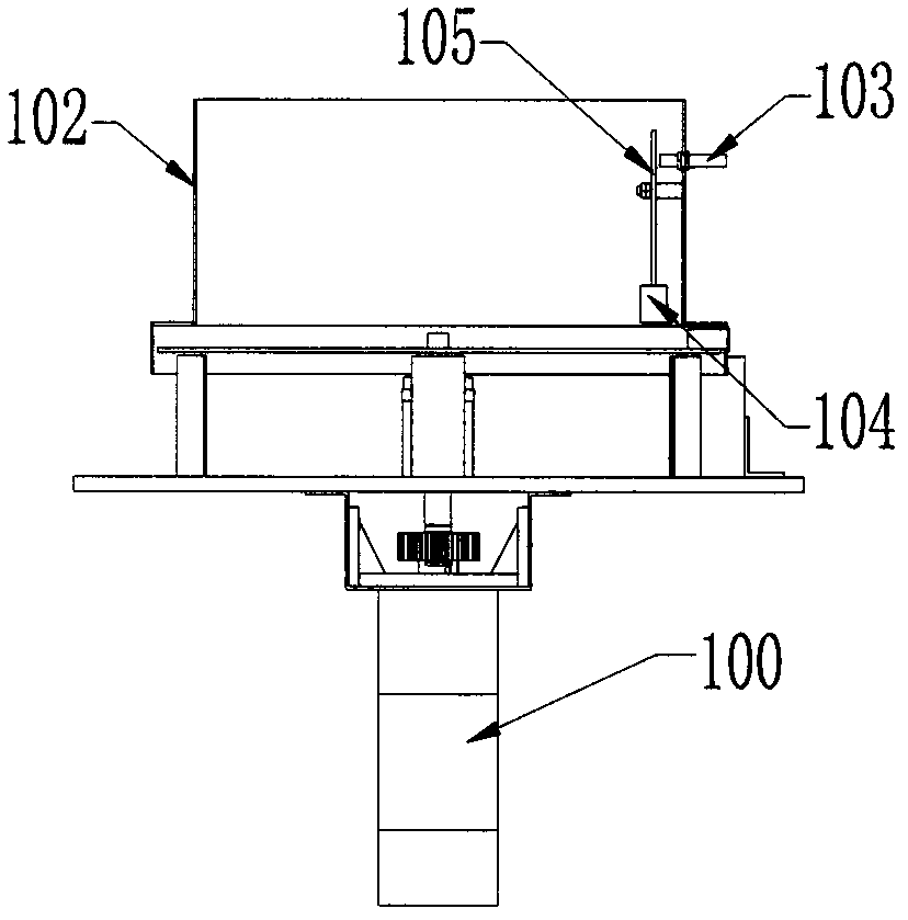
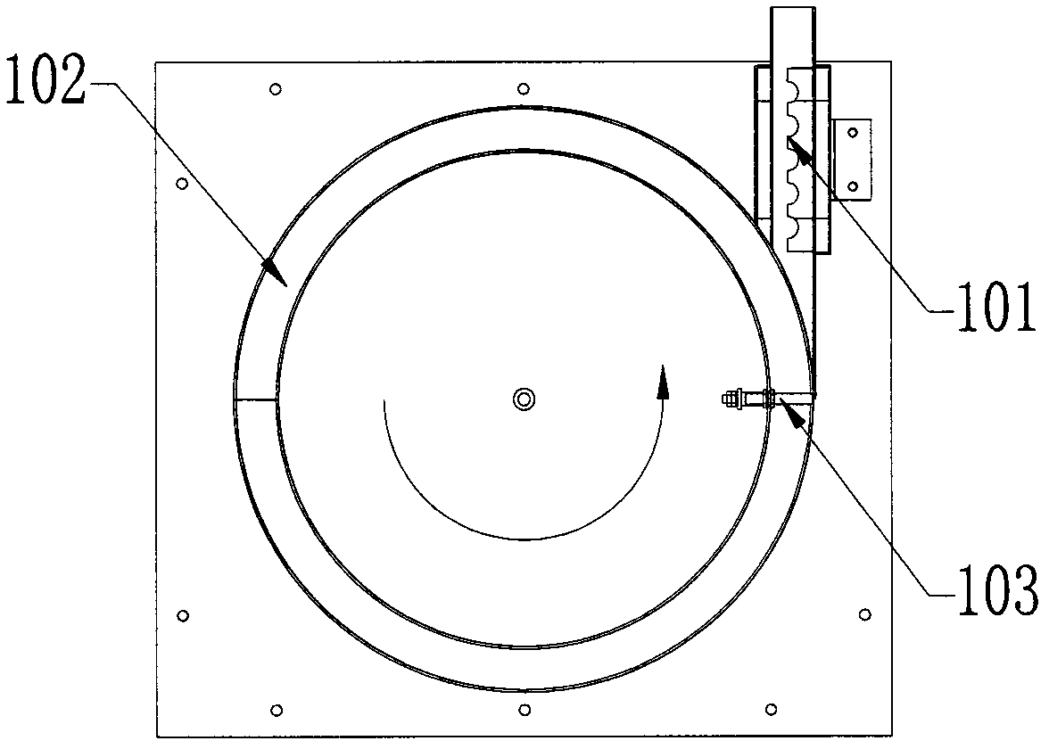
[0032] like Figure 5 and Image 6 The high-speed capping machine includes a main shaft system 1 and a planetary system, the main shaft system 1 includes a first star wheel 112 for continuous feeding and discharging on the main shaft 110, and the planetary system is fixedly connected to the first star wheel 112 above and coaxial with the main shaft 110, the central axis of the planetary assembly 115 in the planetary system corresponds to the central axis of the radial recess on the first star wheel 112, and the planetary assembly 115 moves according to a fixed track , At the lower end of the planetary assembly 115, an intermittent suction head 137' is set.

[0033] Specifically, the first star wheel 112 is fixed on the main shaft 110, and on the ...


PUM


Abstract

The invention discloses a high-speed cap closing machine which comprises a spindle system, a two-shaft system, a three-shaft system, a four-shaft system and a planetary system; the spindle system comprises a first planet wheel which is arranged on a spindle and is used for continuously feeding and discharging; the two-shaft system and the three-shaft system continue to feed for the spindle system; the four-shaft system continues to discharge for the spindle system; the planetary system is fixedly connected above the first planet wheel and shares the same axis with a spindle; a planetary assembly central shaft in the planetary system corresponds to a radial concave central shaft on the first planet wheel; a planetary assembly rotates with the spindle synchronously and peripherally, moves vertically and revolves; and a suction tip for interrupted suction is arranged on the lower end of the planetary assembly. The high-speed cap closing machine continuously feeds and presses and rotates caps for the spindle system, presses and rotates the upper and the lower caps while continuously feeding through the planet system, so that the production cycle is saved, and the production efficiency is maximized.

Description

technical field [0001] The invention relates to a high-speed cap assembly machine. Background technique [0002] At present, the capping machine has been widely used in the fields of food, pharmaceutical and other industrial machinery and equipment to process various types of bottle caps, combined caps and special caps. The products produced have a large output and high quality requirements. [0003] Most of the existing capping machines use the method of pressing first and then spinning to produce bottle caps. Because the pressing and rotating device and the feeding mechanism are in relative motion, when feeding, the pressing and rotating device is in a static state, while When the pressing and spinning device is moving, the feeding mechanism must be stationary, and the feeding, pressing and screwing will take double time consumption, and considering the stability of the entire machine, the time for feeding, pressing and spinning cannot be reduced to too small. The existin...

Claims


Application Information

Patent Timeline
Patent Type & Authority Applications(China)
IPC IPC(8): B23P19/00
Inventor 张著猛谭荣
Owner GUANGZHOU RIJING AUTOMATION MACHINERY CO LTD
Why Eureka
Try Eureka