Al technical title is built by PatSnap Al team. It summarizes the technical point description of the patent document.
A folding tent technology, applied in the field of tents, can solve problems such as easy to change the opening angle, complex structure, unstable tent, etc., and achieve the effect of high tent space, compact structure, and space saving
Inactive Publication Date: 2012-04-25
陈焕奎 +1
View PDF13 Cites 7 Cited by
Summary
Abstract
Description
Claims
Application Information
AI Technical Summary
This helps you quickly interpret patents by identifying the three key elements:
Problems solved by technology
Method used
Benefits of technology
Problems solved by technology
[0004] CN101111653A discloses an automatic folding tent. The automatic folding member used to fix the tent at the center of the top of the tent includes an upper connecting member 130 (hinge seat), a lifting member 150 (plum blossom wheel), and a radial central axis ( sliding rod), and brake 160, the supporting rod 300 is hinged on the lifting member 150, and the torsion member 120 (torsion spring) is hinged to connect the member 130 and the supporting rod 300, and the lifting member 150 is pushed down by the elastic force of the torsion member 120. The tent bracket is stretched, this structure can make the angle of the support rod close to the horizontal line, so the tent space is enlarged, but the structure is complicated, the spring is not easy to assemble, only the tension of the spring makes the support rod stretch, and the support rod is subjected to external force Influence, such as when the strong wind blows the tent, the support pole is easy to change the opening angle, so the tent is not stable
As another example, CN201103269Y discloses the tent top unfolding and retracting device, and CN102146742A discloses the tent pole connector. Under the influence of external force, the support pole is easy to change the opening angle, and the tent is not stable.
Method used
Image
Click on the blue label to locate the original text in one second.
Reading with bidirectional positioning of images and text.
Examples
Embodiment Construction
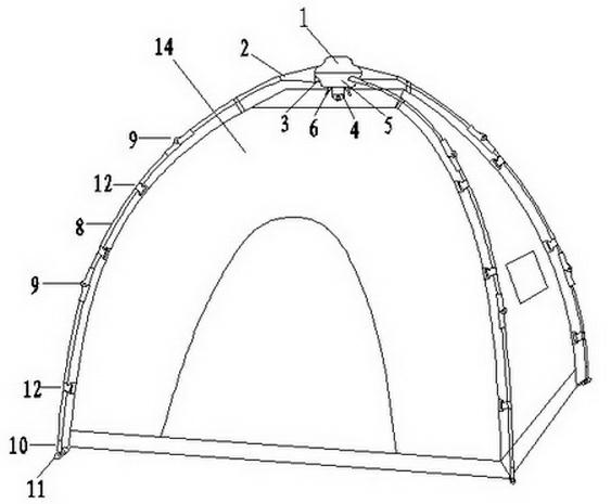
[0039] figure 1 Show an embodiment of the present invention, this folding tent is made up of support and tent cloth 14, and support comprises main hub and more than 4 support rods 8, and main hub is used for connecting support rod 8, makes support rod 8 from multiple Stretching and folding in two directions, the tent cloth 14 is hung on the support rod 8 by the hook 12, and when the support rod 8 is stretched, it drives the tent cloth 14 to stretch, thereby forming a livable inner cavity.
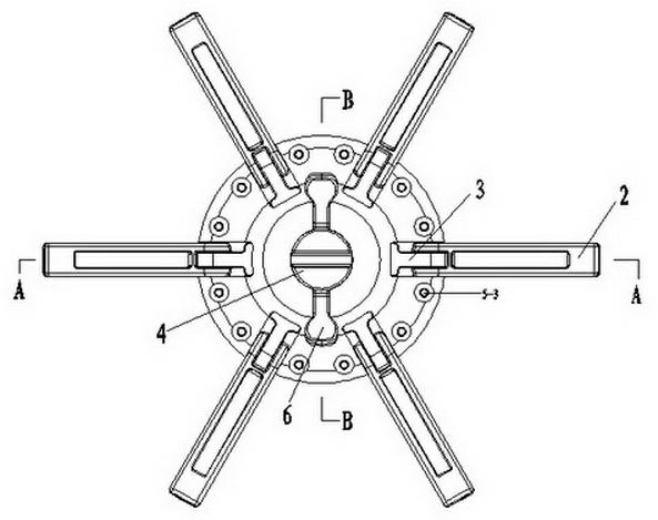
[0040] figure 2 As shown, the main hub consists of an upper cap 1, a compression spring 7, a plum blossom wheel 4, a lower cap 5, more than four main force arms 2, push rods 3 equal in number to the main force arms 2, and two symmetrical lever devices 6 composition.
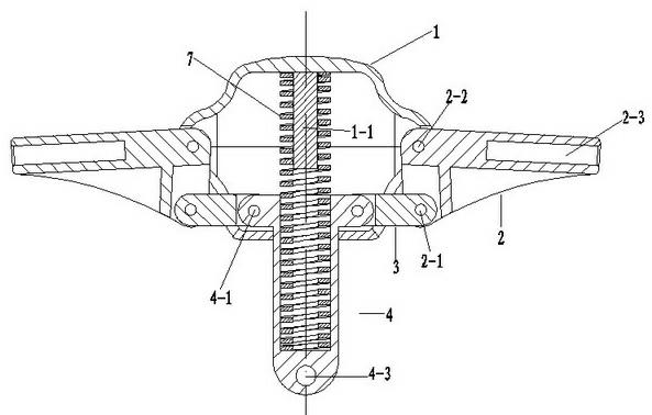
[0041] image 3 As shown, the upper cap 1 is upwardly arched, and there is a guide column 1-1 below the middle part for socketing the spring 7, and the edge of the upper cap 1 has several grooves 1-2 and screw holes 1-3. ...
PUM
Abstract
The invention discloses a foldable-type tent, which is characterized in that: supporting rods can be adequately unfolded to resist the influence of an external force, the foldable-type tent is easy to set and to fold and consists of a bracket and a tent cloth, wherein the bracket comprises a main hinge and a plurality of supporting rods, the main hinge consists of an upper cap, a compression spring, a quincunx wheel, a lower cap, a main force arm and a push rod, the upper cap is connected with the lower cap, the quincunx wheel is arranged inside an inner cavity which is formed by the upper cap and the lower cap, one end of the compression spring is connected to the upper cap, the other end of the compression spring is connected with the quincunx wheel, the middle part of the lower cap is provided with a through hole, a slide shaft is arranged below the quincunx wheel to pass through the through hole, a clamping groove is arranged at the side of the through hole, the quincunx wheel is provided with a clamping block, one end of a lever device is attached to the slide shaft and is arranged below the clamping block, the other end of the lever device is a pressing end, a pivot is embedded inside the clamping groove, one end of the main force arm is connected with the supporting rods, the other end of the main force arm is hinged with the edge of the upper cap, one end of the push rod is hinged with the quincunx wheel, and the other end of the push rod is hinged with the main force arm.
Description
technical field [0001] The invention relates to a tent for outdoor use, in particular to a folding tent that can be automatically opened and easily folded. Background technique [0002] The folding tent is composed of a foldable frame and a tent cloth, and the tent cloth is hung on the frame. The folding bracket is composed of a main hub (or called a hinge seat) and radially distributed support rods, and the support rods are hinged to the main hub through hinge devices. The folding bracket is like an umbrella when it is opened, so it is also called an umbrella tent. [0003] The traditional umbrella tent includes a hinged seat on the top, a sliding rod is connected under the hinged seat, a plum blossom wheel is sleeved on the sliding rod, a spring is sleeved on the sliding rod and its upper end is connected to the hinged seat, the lower end is connected to the plum blossom wheel, and the limiter is fixed on the sliding rod. On the rod and below the plum blossom wheel, seve...
Claims
Application Information
Patent Timeline
Application Date:The date an application was filed.
Publication Date:The date a patent or application was officially published.
First Publication Date:The earliest publication date of a patent with the same application number.
Issue Date:Publication date of the patent grant document.
PCT Entry Date:The Entry date of PCT National Phase.
Estimated Expiry Date:The statutory expiry date of a patent right according to the Patent Law, and it is the longest term of protection that the patent right can achieve without the termination of the patent right due to other reasons(Term extension factor has been taken into account ).
Invalid Date:Actual expiry date is based on effective date or publication date of legal transaction data of invalid patent.