
Special professional lockset

A professional and lock technology, applied in the field of locks, can solve the problems of large, unfavorable, and bulky theft, and achieve the effect of low cost, simple structure, and high security performance

Inactive Publication Date: 2012-04-25
李玉华
View PDF5 Cites 5 Cited by
  • Summary
  • Abstract
  • Description
  • Claims
  • Application Information

AI Technical Summary

Problems solved by technology

The above-mentioned locks generally use a single control device, and the opening and closing of the locks are all controlled by a single control, so that the locks are very likely to be stolen when they are in use, which is not conducive to the use of doors in some special industries. For example, bank cash area safety door, vault door, cash deposit room protective door, ATM protective box door, prison door, etc.
Because the safety requirements for locks on these doors are particularly high, ordinary locks cannot meet the requirements at all, and traditional mechanical locks must have multiple insurance functions, their structure is complex, bulky, and it is not easy to use on small doors; Electronic locks are generally controlled by a motor. When the motor is damaged, the electronic lock cannot work normally, which is not conducive to its use and promotion; and the existing locks with electromechanical integration are still immature, especially the locks with multiple insurance functions. Therefore, a lock with high safety performance is required to meet the requirements for locks in the above-mentioned special fields.

Method used


Image

  • Special professional lockset
  • Special professional lockset
  • Special professional lockset

Examples


Embodiment 1

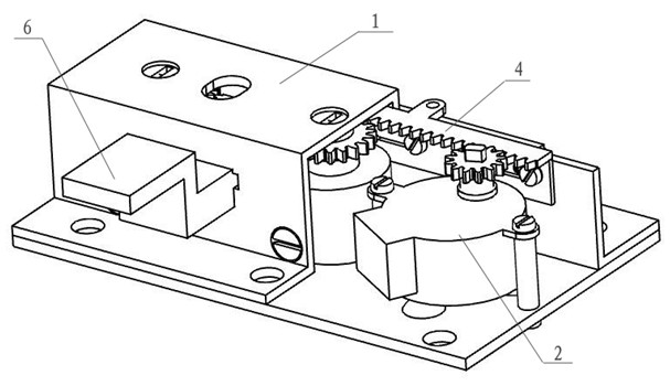
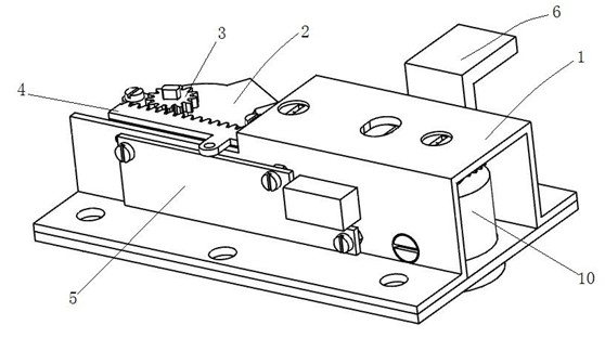
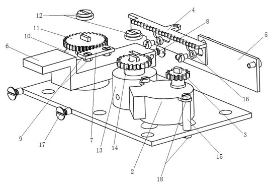
[0023] The lockset of the present invention comprises a housing 1 , a main lock cylinder 10 installed in the housing 1 , a main bolt 6 , a main bolt driving mechanism, a main bolt restricting mechanism and a control circuit thereof.

[0024] Described main deadbolt driving mechanism comprises: the main lock cylinder gear 11 that is arranged on the main lock cylinder 10, the main deadbolt tooth bar 7 that is provided with on the main deadbolt 6, is fixed on the main deadbolt 6 by countersunk head screw nut 9 The main deadbolt rack 7 is also provided with a lock cylinder attachment 12 on the main deadbolt rack 7 . The main deadbolt rack 7 cooperates with the main lock cylinder gear 11 to form a main deadbolt drive mechanism, so the main lock cylinder can drive the main deadbolt 6 to move.

[0025] The main bolt restricting mechanism includes: a limiting opening 19 arranged on the main locking tongue 6 , a main rack 4 cooperating with the limiting opening 19 , a motor 2 and a con...

Embodiment 2

[0029] The opening and locking process of the lockset is similar to that of Embodiment 1, the difference being that: an emergency lock cylinder 13 is also arranged in the housing 1, and an emergency lock cylinder gear 14 is arranged on the emergency lock cylinder 13, and the The emergency lock cylinder gear 14 cooperates with the main rack 4. When the motor 2 fails, the emergency lock cylinder 13 can be controlled by the emergency key to drive the emergency lock cylinder gear 14 to rotate, the emergency lock cylinder gear 14 meshes with the main rack 4, drives the main rack 4 to move, and controls it to cooperate with the limit port 19 , to release the restriction on the main bolt.


PUM


Abstract

The invention discloses a lockset, in particular to a special professional lockset, which comprises a shell, wherein a main lock core, a main lock tongue, a main lock tongue drive mechanism, a main lock tongue limiting mechanism and a control circuit of the main lock tongue limiting mechanism are arranged inside the shell. The main lock core drives the main lock tongue to move through the main lock tongue drive mechanism so as to realize the opening and the locking of a door, and the main lock tongue limiting mechanism is connected onto the control circuit and limits or allows the movement ofthe lock tongue. The lockset has a simple structure, high reliability, high security performance and low cost; and the mechanical lock is matched with the electronic lock, so the special professionallockset has a double insurance function and is suitable for being popularized in finance and other special industries.

Description

technical field [0001] The invention relates to a lock, in particular to a special professional lock with double insurance functions. Background technique [0002] Currently used locksets include mechanical locks and electronic locks, and there are also a few locksets with electromechanical integration. The above-mentioned locks generally use a single control device, and the opening and closing of the locks are all controlled by a single control, so that the locks are very likely to be stolen when they are in use, which is not conducive to the use of doors in some special industries. For example, bank cash area safety door, vault door, banknote adding room protective door, ATM protective box door, prison door, etc. Because the safety requirements for locks on these doors are particularly high, ordinary locks cannot meet the requirements at all, and traditional mechanical locks must have multiple insurance functions, their structure is complex, bulky, and it is not easy to u...

Claims


Application Information

Patent Timeline
Patent Type & Authority Applications(China)
IPC IPC(8): E05B47/06E05B17/20E05B17/22E05B63/14
Inventor 李玉华
Owner 李玉华
Learn More