Real-time monitoring device for soil erosion of ravine

A real-time monitoring and gully technology, applied in measurement devices, liquid/fluid solid measurement, measurement flow/mass flow, etc., can solve the problems of large cumulative error, high cost, complicated system, etc., to reduce cumulative error and accurate water flow. , the effect of measuring the size of the water flow

Inactive Publication Date: 2012-04-25
辽宁省水土保持研究所
View PDF4 Cites 4 Cited by
  • Summary
  • Abstract
  • Description
  • Claims
  • Application Information

AI Technical Summary

Problems solved by technology

[0003] The Chinese invention patent application number is 200310110900.3, the inventor He Binghui, and the patent titled "Nine-hole diversion water and soil loss monitoring system on natural slope surface" discloses a monitoring device. The invention sets up 9 outfalls in Shenshadang And a drain that flows into the next level of sand sinking, because the drain that flows into the next level of sand sinking is not in the same position as the 9 drains, and the process of water inflow and outflow forms a different flow rate in the sinking sand , therefore, the amount of water flowing into the next level of sand sinking can not be equal to one-tenth of the flow of the sinking sand, because the sinking of sand is multi-level, so the cumulative error is huge; in addition, the method for measuring the soil content of the invention is It is also inaccurate to use the silt content of the first-level sand sink as a standard, because although the sand sink can deposit most of the silt, there are still some that flow into the next level of sand sink, which is not considered in this invention, and this The sediment monitoring method requires sampling and drying, and cannot monitor the soil content in real time
However, the real-time monitoring devices controlled by computers are not only expensive, but more importantly, they are not suitable for field operations due to the complexity of the system.

Method used


Image

  • Real-time monitoring device for soil erosion of ravine
  • Real-time monitoring device for soil erosion of ravine
  • Real-time monitoring device for soil erosion of ravine

Examples


Embodiment Construction

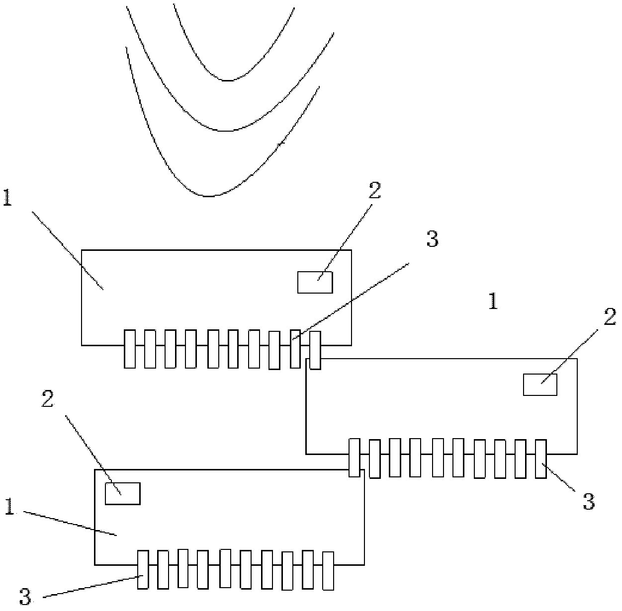
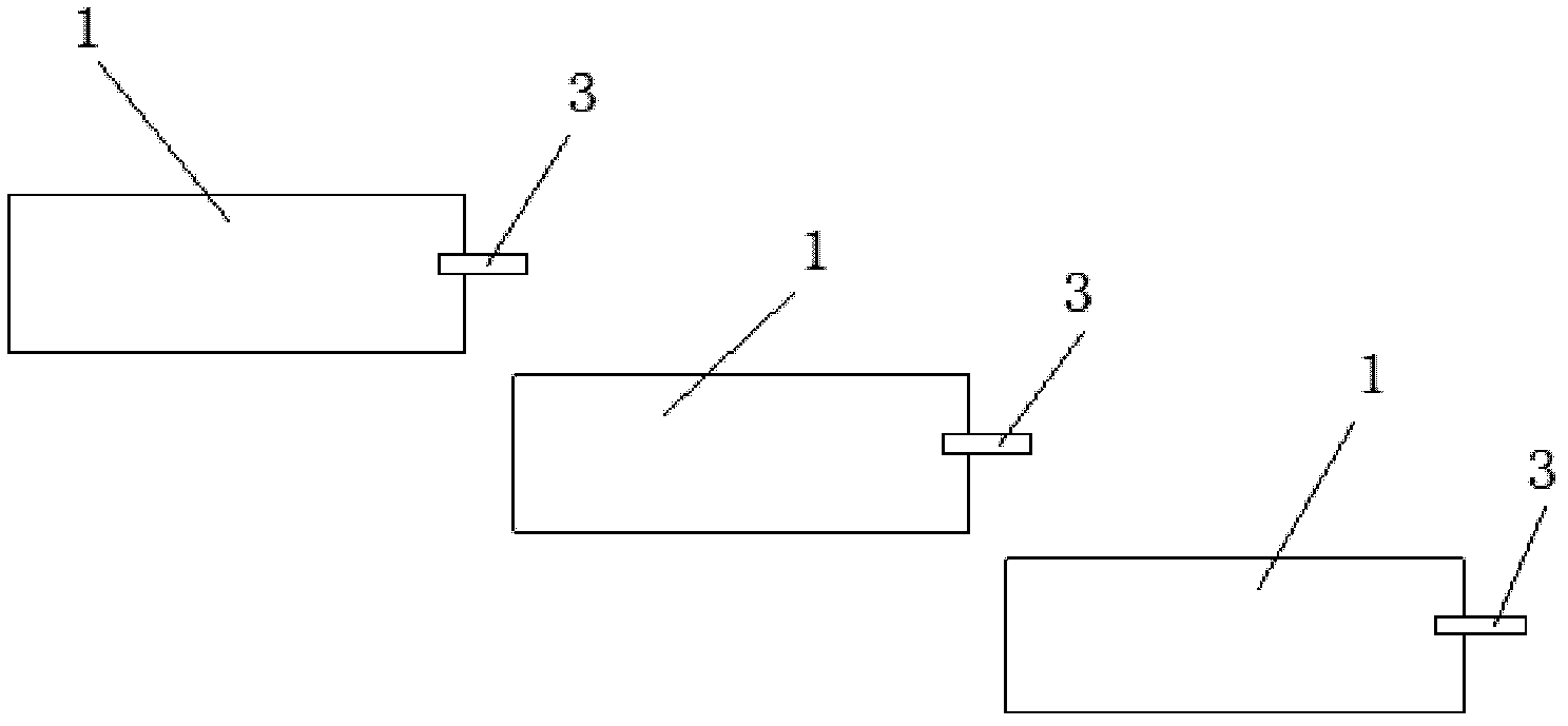
[0012] The present invention is specifically described below in conjunction with accompanying drawing, as figure 1 , 2 , 3, and 4 show that the present invention includes a water diversion ditch, a stilling area, and a grit chamber 1, and the water in the ditch is introduced into the stilling area by the water diversion ditch, and the water in the stilling area flows into the grit chamber 1, and the desilter There are multiple grit chambers 1 arranged from high to low. The grit chamber 1 is provided with drain pipes 3, and each grit chamber 1 is provided with 10 drain pipes 3. The drain pipes 3 are arranged on the same side, and each The diameter and length of the drainpipe 3 are equal, wherein a drainpipe 3 of the grit chamber 1 on the upper floor is discharged into the grit chamber 1 of the next floor;

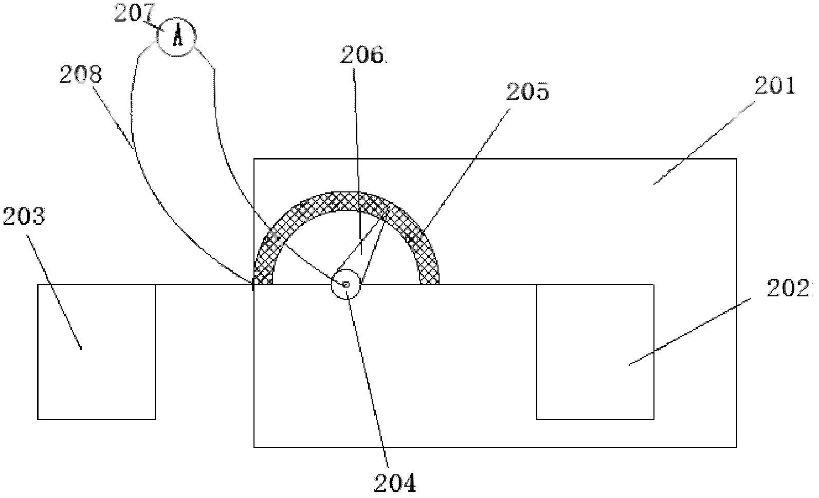
[0013] In order to realize real-time monitoring of soil content, each of the grit chambers is provided with a current type soil monitor 2, and the current type soil monitor...


PUM


Abstract

The invention discloses a real-time monitoring device for the soil erosion of a ravine, which comprises a flume, a force counteracting region and a plurality of settling basins, wherein the flume leads water in the ravine to the force counteracting region, water in the force counteracting region flows into the settling basins, the settling basins are arranged from high to low, and each settling basin is provided with a plurality of drain pipes. The real-time monitoring device is characterized in that each settling basin is provided with 10 drain pipes, the drain pipes are arranged at the same side, the diameter and the length of each drain pipe is equal to one another, one drain pipe of the upper-layer settling basin is discharged into the lower-layer settling basin, and each settling basin is provided with a current type soil monitor. The real-time monitoring device has the advantages that the size of flow can be accurately monitored, the accumulative error can be reduced, the specific numerical value of the soil erosion can be timely monitored, and the device is suitable for the field work.

Description

technical field [0001] The invention relates to the technical field of water and soil monitoring, in particular to a water and soil loss monitoring device. Background technique [0002] With the increasing impact of production technology on the natural environment, the living environment of human beings is facing a huge test, especially the climate is more obviously affected by various waste gases emitted by humans. Therefore, soil and water conservation and forestry construction are becoming more and more important. important. The monitoring of water and soil loss is the basis of the above work, and the monitoring of water and soil loss can provide the necessary design basis for the formulation of water and soil conservation projects. [0003] The Chinese invention patent application number is 200310110900.3, the inventor He Binghui, and the patent titled "Nine-hole diversion water and soil loss monitoring system on natural slope surface" discloses a monitoring device. The...

Claims


Application Information

Patent Timeline
Patent Type & Authority Applications(China)
IPC IPC(8): G01F1/74
Inventor 舒乔生谢立亚贾天会郑国相蒋春光任丽华林素兰
Owner 辽宁省水土保持研究所
Why Eureka
Try Eureka